

Method of cutting glass substrate material
a technology of glass substrate and cutting plane, which is applied in the direction of identification means, instruments, manufacturing tools, etc., to achieve the effect of high-quality and hard-to-chip cutting plan
Inactive Publication Date: 2005-11-24
THK CO LTD +1
View PDF7 Cites 32 Cited by
- Summary
- Abstract
- Description
- Claims
- Application Information
AI Technical Summary
Benefits of technology
[0007] Therefore, an object of the present invention is to provide a method for cutting the glass substrate member, which is capable of cutting the glass substrate member while forming a scribe line with the “scriber” and obtaining a high-quality and hard-to-chip cutting plane.
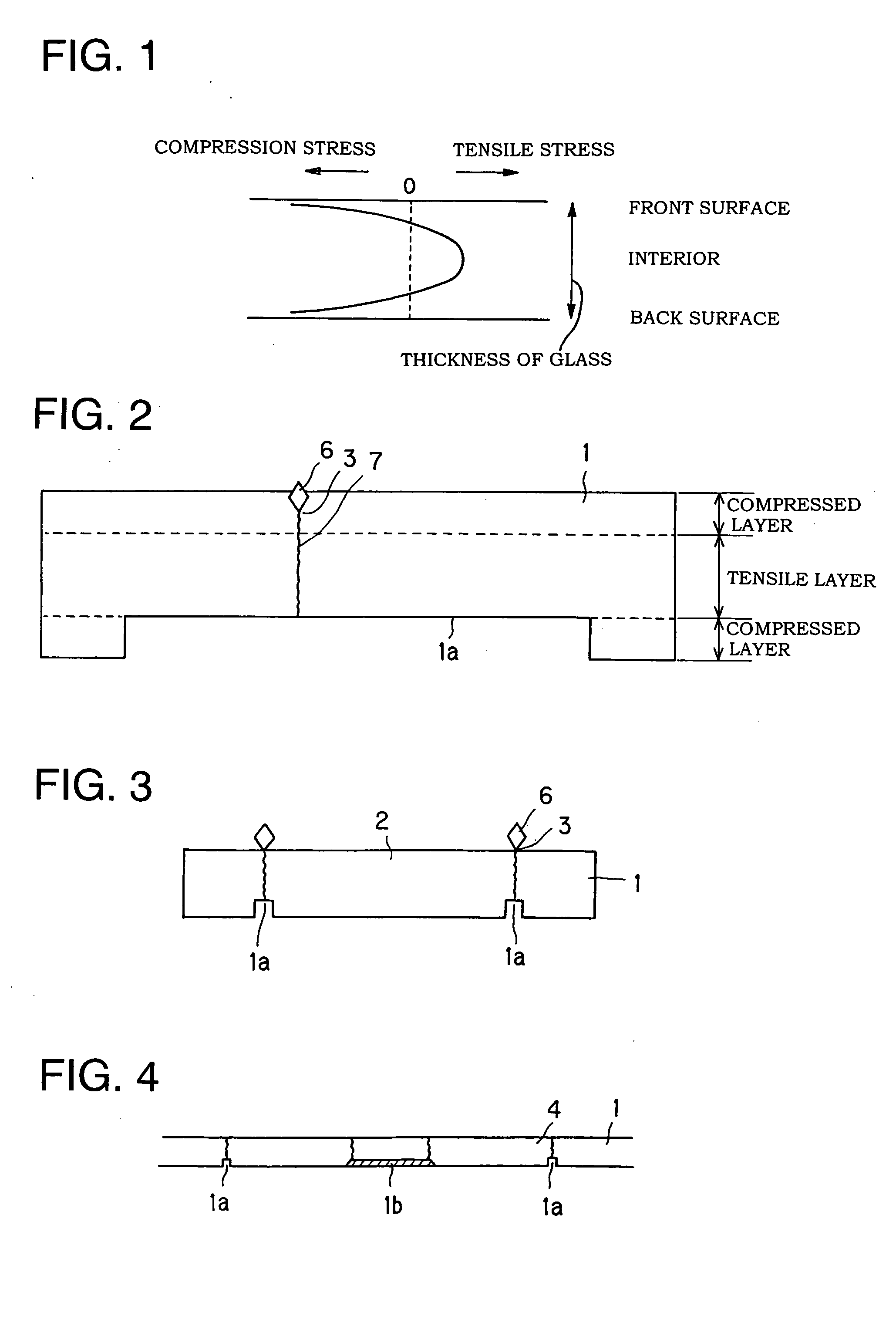
[0008] When a molten glass is cooled down to become glass, compression stress occurs in the vicinity of the surface of the glass substrate member and tensile stress occurs in the interior of the glass substrate member. Such a phenomenon in which a compressed layer is generated in the vicinity of the surface and a tensile layer is generated in the interior thereof is inherent in the glass substrate member. The inventor of the present invention has paid attention to the fact that a crack does not easily expand in the compressed layer, but the crack expands rapidly in the tensile layer, and found that a high-quality and hard-to-chip cutting plane can be obtained by removing previously the compressed layer from the back surface side of the glass substrate member, wherein the crack is hard to break therethrough, and then forming the scribe line that produces the crack extending to the back surface of the glass substrate member on the front surface of the glass substrate member.
[0011] With respect to a step for forming the scribe line on the front surface of the glass substrate member, there is a step for moving a tool coming in contact with the glass substrate member over the front surface of the glass substrate member, while vibrating same in a direction intersecting the front surface of the glass substrate member. When the scribe line is formed in this manner, the crack is easy to generate along the scribe line in the vertical direction to the front surface of the glass substrate member.
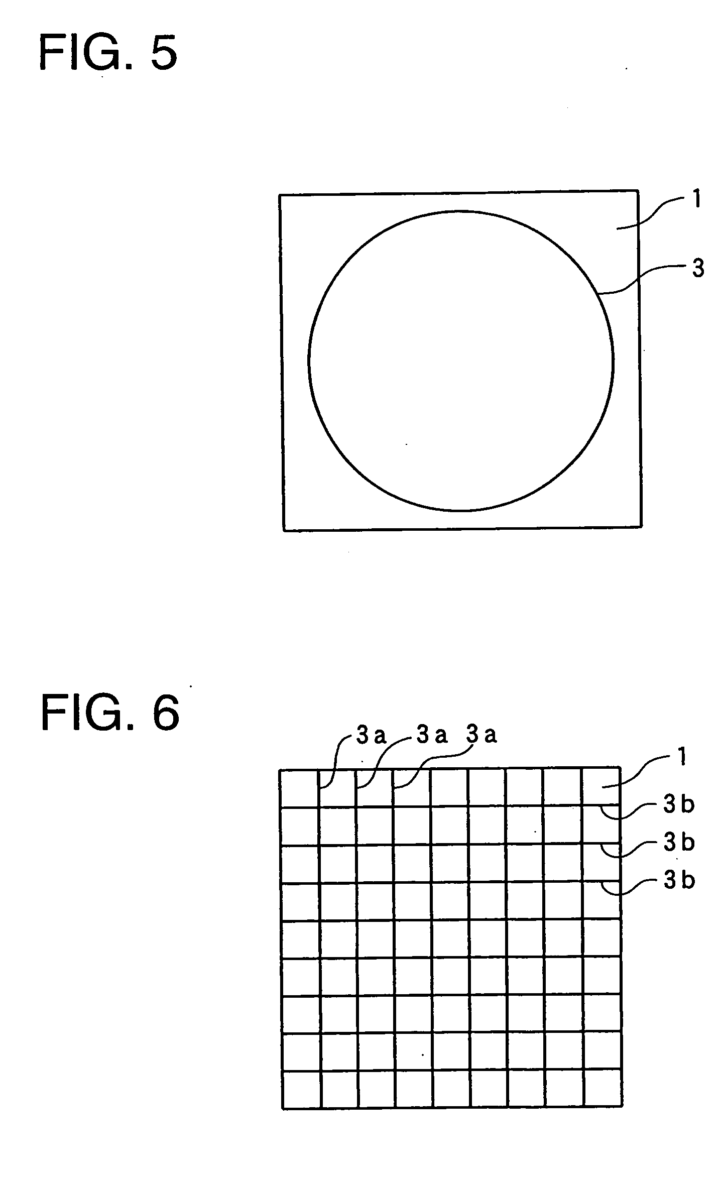
[0013] The above-mentioned removing step may comprise removing only the part corresponding to the scribe line, so as to leave the compressed layer on the back surface in a maximum amount and enhance the strength of the cut glass substrate.
Problems solved by technology
Moreover, this method may generate chipped recesses (or broken edges) on the back surface of the glass substrate member when the cutting operation is performed with the use of the breaker, thus requiring a chamfering step for grinding the chipped part.
Method used
View moreImage
Smart ImageViewing Examples

Examples
example
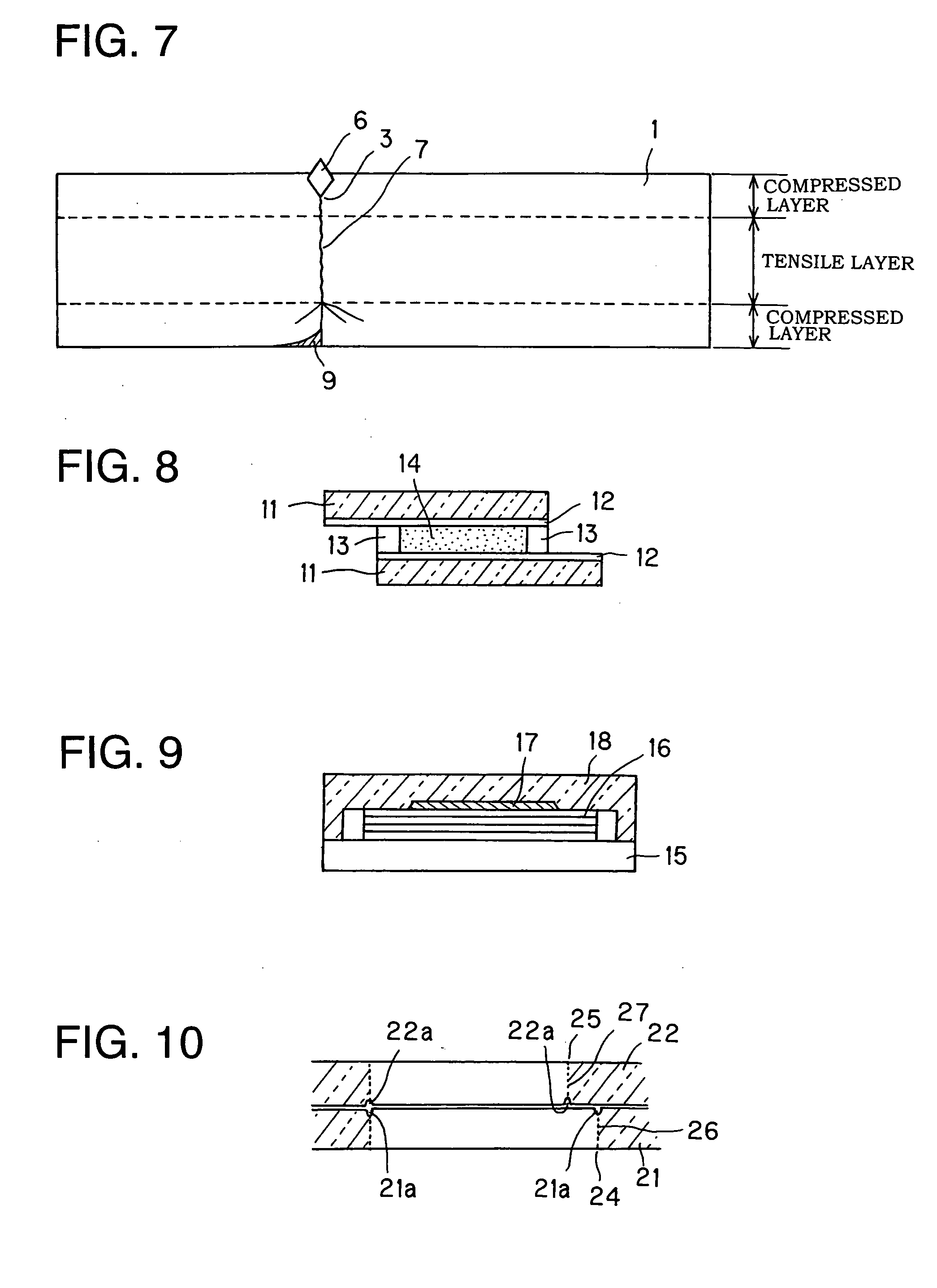
[0043]FIG. 11 shows an enlarged view showing a cutting plane of the glass substrate member cut by the cutting method according to this embodiment. The compressed layer on the back surface side of the glass substrate member is removed by chemical polishing and the scribe lines, along which cracks extend to the back surface, are formed by using a vibrating tool at the front surface. A high-quality cutting plane without chipped recess or fine cracks can be obtained.
Login to View More PUM
 Abstract
There is provided a method for cutting a glass substrate member capable of cutting the glass substrate member while forming a scribe line with a “scriber” and also obtaining a high-quality and hard-to-chip cutting plane. The cutting method for the glass substrate member according to the present invention comprises a removing step for removing a part or whole of a back surface portion of the glass substrate member; and a scribing step for forming a scribe line that produces a crack on a front surface of the glass substrate member. The crack extends to a back surface of the glass substrate member.
Description
TECHNICAL FIELD [0001] The present invention relates to a method for cutting a glass substrate member. BACKGROUND ART [0002] For example, a liquid crystal display is generally fabricated by sealing two thin glass substrates at their periphery with a sealant and injecting liquid crystal between the glass substrates. An organic EL display is generally fabricated by deposition-forming thin films such as electrodes and luminescent layers on a thin glass substrate by deposition or the like [0003] A glass substrate used for such a display is required to be smooth, free of undulation and thin. Typical methods of manufacturing glass include, for example, a floating method of pouring glass onto melted tin to form glass in the form of plate and a down-drawing method of discharging melted glass from a furnace and drawing it from a slit between rollers. [0004] Through the above-mentioned manufacturing processes, the glass is manufactured in the form of glass substrate members having a predeterm...
Claims
Login to View More Application Information
Patent Timeline
 IPC IPC(8): C03B33/023G02F1/1333C03B33/037C03B33/04C03B33/07C03C15/00G09F9/30H01L51/50H05B33/02
CPCC03B33/023C03B33/04C03C15/00C03B33/076C03B33/07C03B33/037
InventorISHIKAWA, HIROKAZAHAYASHI, TOSHIO
OwnerTHK CO LTD