Remote chamber methods for removing surface deposits

a technology of surface deposits and remote chambers, applied in the direction of coatings, decorative arts, chemical vapor deposition coatings, etc., can solve the problems of pecvd equipment manufacturers

Inactive Publication Date: 2005-11-24
MASSACHUSETTS INST OF TECH
View PDF15 Cites 13 Cited by
  • Summary
  • Abstract
  • Description
  • Claims
  • Application Information

AI Technical Summary

Benefits of technology

[0008] The present invention relates to a method for removing surface deposits, said method comprising: (a) activating in a remote chamber a gas mixture comprising oxygen and fluorocarbon, wherein the molar ratio of oxygen and fluorocarbon is at least 1:4, using sufficient power for a sufficient time such that said gas mixture reaches a neutral temperature of at least about 3,000 K to form an activated gas mixture; and thereafter (b) contacting said activated gas mixture with the surface deposits and thereby removing at least some of said surface deposits.

Problems solved by technology

Secondly, it was commonly found that fluorocarbon discharges produced “polymer” depositions that require more frequent wet cleans to remove these deposits that build up after repetitive dry cleans.
In fact, the PECVD equipment manufacturers tested remote cleans based on fluorocarbon discharges, but to date have been unsuccessful because of polymer deposition in the process chambers.

Method used


Image

  • Remote chamber methods for removing surface deposits
  • Remote chamber methods for removing surface deposits
  • Remote chamber methods for removing surface deposits

Examples


example 1

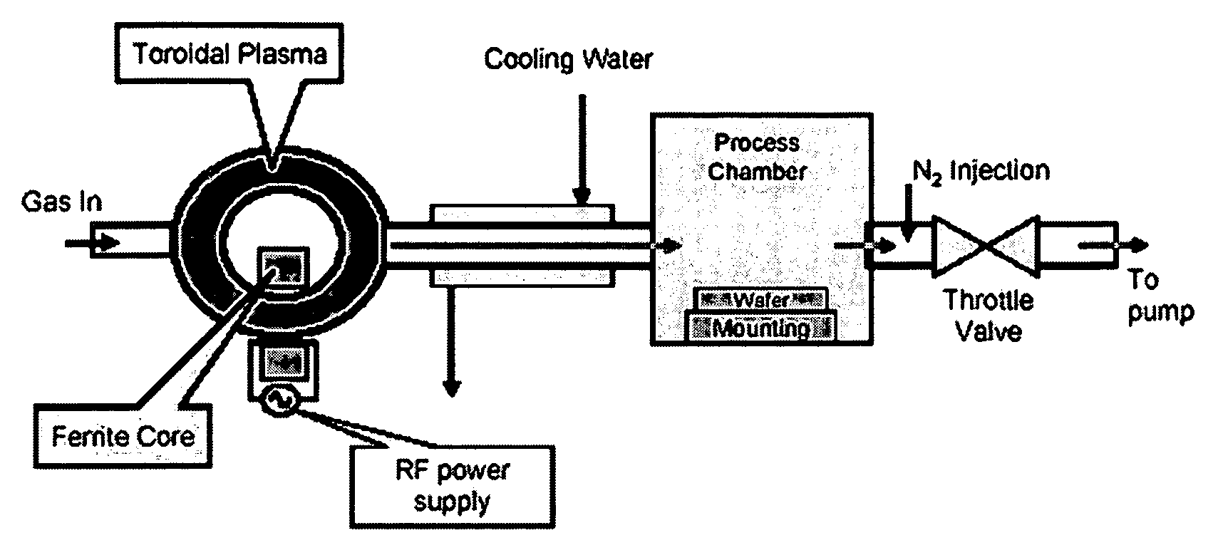
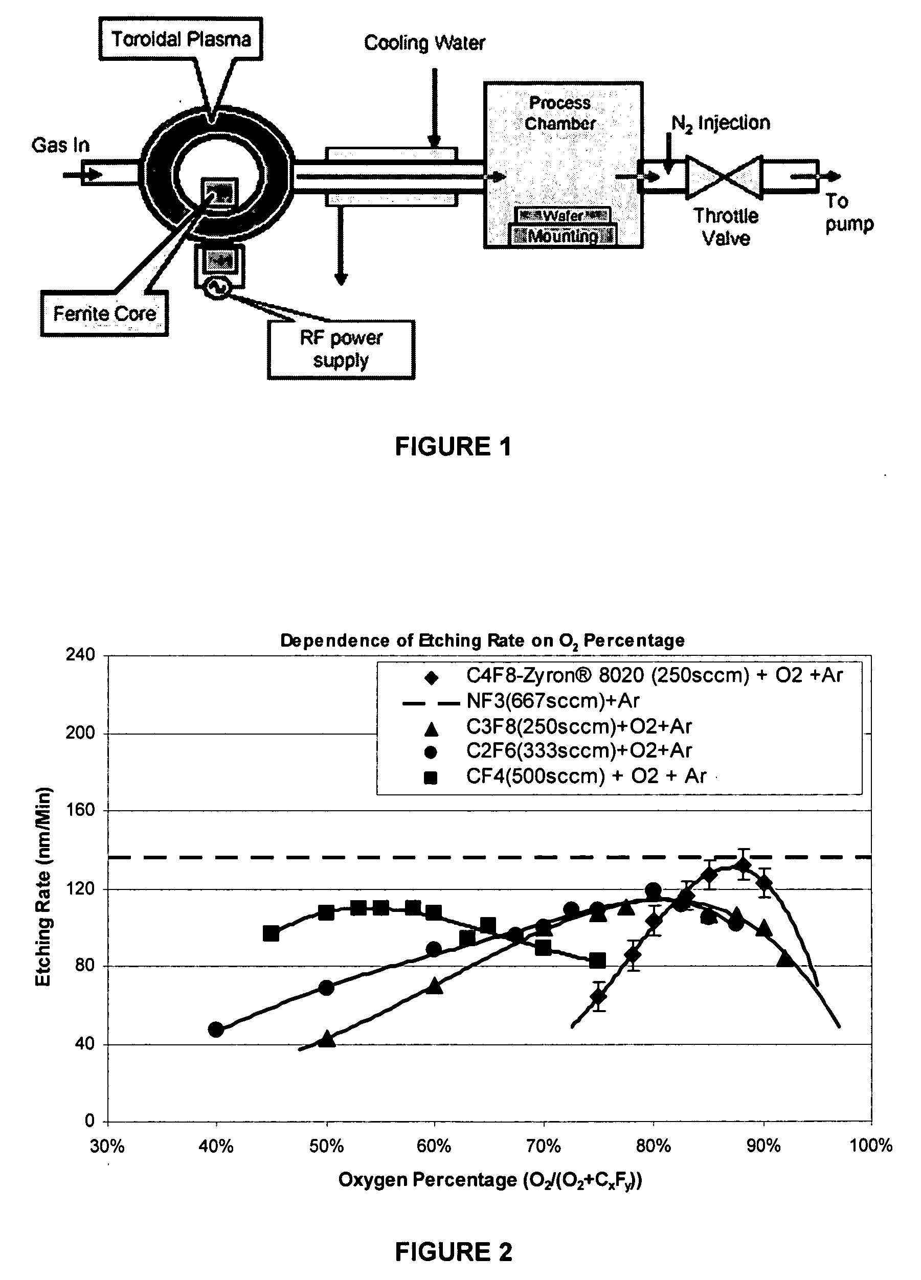
[0028] The feeding gas composed of O2, perfluorocarbon and Ar, wherein the perfluorocarbon is Zyron® 8020 (C4F8), C3F8, C2F6, or CF4. The flow rates of perfluorocarbons in this Example were adjusted so that the molar flow rate of elemental fluorine into the remote chamber was the same for all mixtures. In this Example, the flow rates for C4F8, C3F8, C2F6, and CF4 were 250, 250, 333 and 500 sccm respectively, which are all equivalent to 2000 sccm of elemental fluorine. The percentage flow rate of O2 to the total of O2 and perfluorocarbon was changed to detect the etching rate dependence on the O2 percentage. See FIG. 2. The total feeding gas flow rate was fixed at 4000 sccm by adjusting argon flow. Nitrogen was added between the process chamber and the pump at a flow rate of 20,000 sccm. Chamber pressure is 2 torr. The feeding gas was activated by 400 KHz RF power to a neutral temperature of more than 5000 K. The activated gas then entered the process chamber and etched the SiO2 surf...

example 2

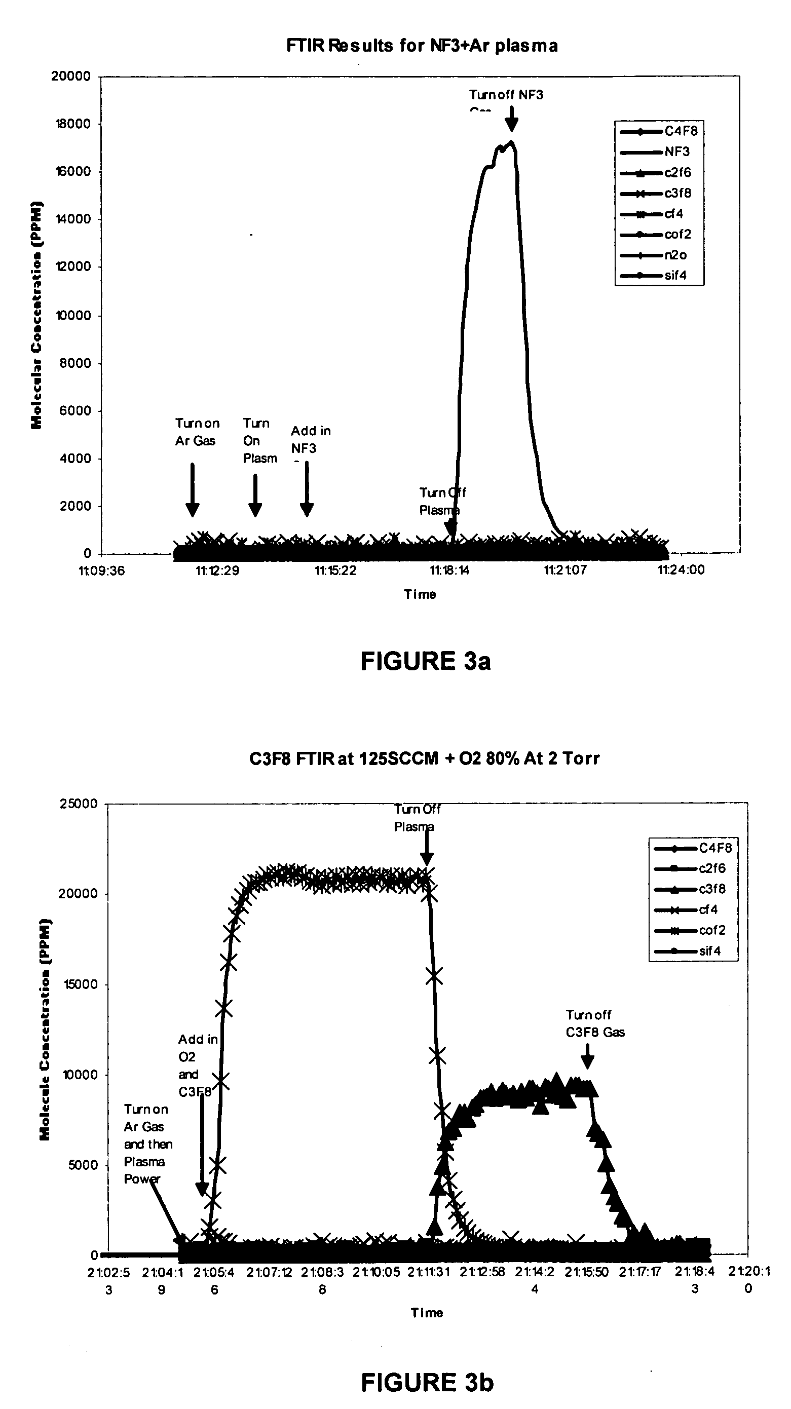
[0031] The common experimental conditions for FIGS. 3a, 3b, 3c and 3d are described in the following paragraph below.

[0032] Chamber pressure was 2 torr. The feeding gas was activated by 400 KHz RF power to a neutral temperature of more than 3000 K for NF3 gas mixture and more than 5000K for perfluorocarbon gas mixtures. The activated gas then entered the process chamber and etched the SiO2 surface deposits on the mounting with the temperature controlled at 100° C. FTIR was used to measure the concentration of emission species in the pump exhaust.

[0033] As for FIG. 3a, the feeding gas composed of NF3 and Argon with flow rates of 333 sccm and 3667 sccm respectively.

[0034] As for FIG. 3b, the feeding gas composed of 125 sccm of C3F8, 500 sccm of O2 and 3375 sccm of Argon.

[0035] As for FIG. 3c, the feeding gas composed of 125 sccm of C4F8, 1125 sccm of O2 and 2750 sccm of Argon.

[0036] As for FIG. 3d, the feeding gas composed of 250 sccm of CF4, 306 sccm of O2 and 3444 sccm of Argon...

example 3

[0039]FIGS. 4a and 4b demonstrate the effects of perfluorocarbon flow rate and O2 percentage (O2 / (CxFy+O2)) on the concentration of emission gases. For both Figures, from left to right the bars in each group indicate emission concentrations of C4F8, C2F6, C3F8, CF4 and COF2. For the experiments of FIG. 4a, the C4F8 flow rates was 93.75 sccm, 125 sccm, 187.5 sccm or 250 sccm, as shown at axis X of the Figure. The corresponding O2 flow rates are 656, 875, 1313 and 1750 sccm, respectively. The total feeding gas flow rate was fixed at 4000 sccm by adjusting Argon flow. Chamber pressure was 2 torr. The feeding gas was activated by 400 KHz RF power to a neutral temperature of more than 5000 K. The activated gas then entered the process chamber and etched the SiO2 surface deposits on the mounting with the temperature controlled at 100° C. FTIR was used to measure the concentration of emission species in the pump exhaust.

[0040] For the experiments of FIG. 4b, the C4F8 flow rates was 250 sc...


PUM

PropertyMeasurementUnit
temperatureaaaaaaaaaa
pressureaaaaaaaaaa
pressureaaaaaaaaaa

Abstract

The present invention relates to an improved remote plasma cleaning method for removing surface deposits from a surface, such as the interior of a deposition chamber that is used in fabricating electronic devices. The improvement involves using an activated gas with high neutral temperature of at least about 3,000 K. The improvement also involves optimizing oxygen to fluorocarbon ratios for better etching rates and emission gas control.

Description

BACKGROUND OF THE INVENTION [0001] 1. Field of the Invention [0002] The present invention relates to methods for removing surface deposits by using an activated gas created by remotely activating a gas mixture comprising of oxygen and fluorocarbon. More specifically, the present invention relates to methods for removing surface deposits from the interior of a chemical vapor deposition chamber using an activated gas created by remotely activating a gas mixture comprising of oxygen and perfluorocarbon. [0003] 2. Description of Related Art [0004] Remote plasma sources for the production of atomic fluorine are widely used for chamber cleaning in the semiconductor processing industry, particularly in the cleaning of chambers used for Chemical Vapor Deposition (CVD) and Plasma Enhanced Chemical Vapor Deposition (PECVD). The use of remote plasma sources avoids some of the erosion of the interior chamber materials that occurs with in situ chamber cleans in which the cleaning is performed by...

Claims


Application Information

Patent Timeline
Patent Type & Authority Applications(United States)
IPC IPC(8): B44C1/22C23C16/44H01L21/302H01L21/311
CPCH01L21/31116C23C16/4405
Inventor SAWIN, HERBERT H.BAI, BO
Owner MASSACHUSETTS INST OF TECH
Why Eureka
Try Eureka