Quartz glass lamp and method for forming a quartz glass lamp

a technology of quartz glass and glass lamps, which is applied in the manufacture of electric discharge lamps, electric discharge tubes/lamps, electrical apparatus, etc., can solve the problems of high deviation in seal quality and weakness of end regions of lamps constructed in accordance with the above method

Active Publication Date: 2005-11-24
HERAEUS NOBLELIGHT LTD
View PDF12 Cites 3 Cited by
  • Summary
  • Abstract
  • Description
  • Claims
  • Application Information

AI Technical Summary

Benefits of technology

[0017] Lamps constructed in accordance with the above method have been found to possess a weakness in the end regions thereof, where a GS to GS seal has been formed. Investigations have indicated possible

Problems solved by technology

Lamps constructed in accordance with the above method have been found to possess a weakness in the end

Method used


Image

  • Quartz glass lamp and method for forming a quartz glass lamp
  • Quartz glass lamp and method for forming a quartz glass lamp

Examples


Embodiment Construction

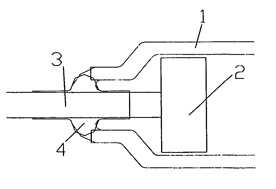
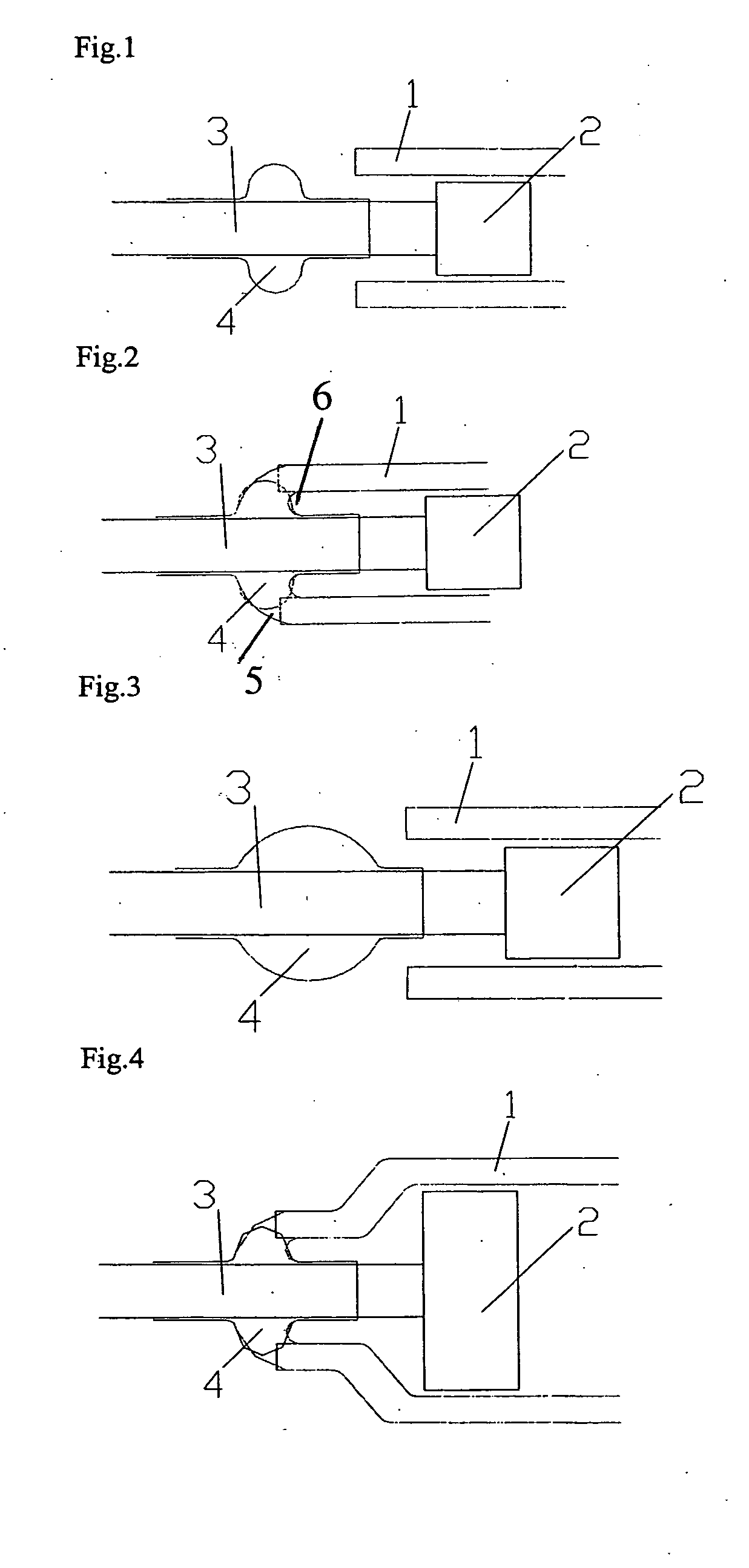
[0030] A preferred embodiment of the method of present invention comprises the following steps: [0031] (1) A tungsten pin 3 is coated with sealing glass comprising a sheath and bead, the bead 4 being larger than the internal diameter of the fused silica / quartz tube 1, but no larger than the external diameter of the fused silica / quartz tube 1 (FIG. 1). The fused silica / quartz tube 1 forms the lamp housing and typically has a 0.5 mm wall thickness; [0032] (2) The bead 4 is heated to a soft state while rotating it on a lathe and is inserted into the annulus of the lamp housing tube 1 to form a seal 5; [0033] (3) After the insertion, the seal 5 is then heated to allow the sealing glass to wet on and to fuse with the housing tube (FIG. 2); and [0034] (4) After fusing the bead 4 to the quartz tube 1, both internally and to the end of the quartz tube, and while the sealing glass is molten, an internal positive pressure is applied, causing the sealing glass inside the quartz tube to move ba...


PUM


Abstract

A method is provided for formation of a glass to metal seal at one end of a quartz lamp tube, as part of the process of manufacturing a complete lamp tube. The method involves a direct sealing of the tube of quartz glass with a seal material surrounding an electrode or its electrical feed through. The seal material may be in the form of a bead having a generally elliptical or spherical shape.

Description

BACKGROUND OF THE INVENTION [0001] This invention relates to mechanically strong and leak-free sealing of bodies comprising a tube of fused silica and a high temperature material of an electrical feed through, such as are used as flash lamps and laser lamps, and in particular to the construction of the ends of such lamps and a method of effecting the sealing of electrodes into the ends thereof. [0002] According to UK published patent application GB 23 08 226 or U.S. Pat. No. 5,979,187, flash and laser lamps are generally constructed from a tube of fused silica / quartz, the opposite ends of which contain metal electrodes to which electrical operating power is supplied via conductive supports, which also serve to mount the lamp in a lamp holder, when in use. [0003] Due to the different coefficients of expansion of metal and fused silica / quartz, special materials have been developed for interposing between the metal conductive supports for the electrodes and the tube wall of such lamps,...

Claims


Application Information

Patent Timeline
IPC IPC(8): H01J5/32H01J9/32H01J17/18H01J61/36
CPCH01J61/36H01J9/323
Inventor HUXLEY, LAWRENCE
Owner HERAEUS NOBLELIGHT LTD
Why Eureka
Try Eureka