Microstrip directional coupler

a directional coupler and microstrip technology, applied in the field of directional couplers, can solve the problems of high cost and large size, waveguide components, key factors of cost and size, etc., and achieve the effect of limiting the mismatch of even and odd modes and high directivity

Inactive Publication Date: 2005-11-24
REVEAL IMAGING
View PDF4 Cites 20 Cited by
  • Summary
  • Abstract
  • Description
  • Claims
  • Application Information

AI Technical Summary

Benefits of technology

[0015] In accordance with embodiments of the present invention, a compact, high-directivity microstrip coupler used for microwave frequencies has a coupling section that is less than a quarter wavelength, which aids in limiting...

Problems solved by technology

Once again, however, cost and size are key factors.
These types of waveguide components are not preferred in some applications because of their high cost and large size.
Stripline couplers typically have not been preferred because of their increased complexity, substantial assembly time in manufacture, added material costs compared to other commercially available couplers, and increased labor costs as...

Method used


Image

  • Microstrip directional coupler
  • Microstrip directional coupler
  • Microstrip directional coupler

Examples


Embodiment Construction

[0033] The present invention will now be described more fully hereinafter with reference to the accompanying drawings, in which preferred embodiments of the invention are shown. This invention may, however, be embodied in many different forms and should not be construed as limited to the embodiments set forth herein. Rather, these embodiments are provided so that this disclosure will be thorough and complete, and will fully convey the scope of the invention to those skilled in the art. Like numbers refer to like elements throughout.

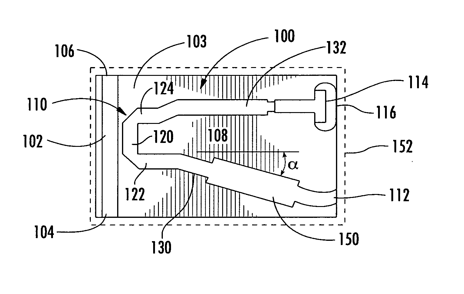
[0034] A compact, high-directivity microstrip coupler usable at microwave frequencies in accordance with an embodiment of the invention is set forth. In one aspect, it can achieve a high-directivity of greater than 15 dB and enable high-performance in a microstrip environment. It can have a short coupling section and a compact size, and matched even and odd modes. This type of microstrip directional coupler does not require fine geometries. It is compati...


PUM


Abstract

A microwave directional coupler includes a microstrip conductor formed on a dielectric substrate and forming a main transmission line having in and out ports that receive signals to be coupled. A substantially U-shaped microstrip conductor is formed over the dielectric substrate adjacent to the main transmission line and forms a secondary transmission line having a coupling section and coupler port. A load resistor is formed within the secondary transmission line, and the coupling section is less than a quarter wavelength of a center frequency.

Description

RELATED APPLICATION [0001] This application is based upon prior filed copending provisional application Ser. No. 60 / 572,640 filed May 19, 2004.FIELD OF THE INVENTION [0002] This invention relates to the field of directional couplers, and more particularly, this invention relates to microstrip directional couplers operative at microwave frequencies. BACKGROUND OF THE INVENTION [0003] Directional couplers often are formed as waveguide, stripline, or microstrip directional couplers. Typical waveguide directional couplers are used primarily to sample power for measurements. For example, two waveguides could be located side-by-side, one above the other, parallel, or crossing each other. Holes can be drilled in a common wall to permit coupling between the waveguides. [0004] A stripline or microstrip coupler, on the other hand, usually has a main transmission line in close proximity to a secondary transmission line. In some designs, quarter wavelength coupling sections are added to either ...

Claims


Application Information

Patent Timeline
IPC IPC(8): H01P5/18
CPCH01P5/185
Inventor HUBERT, JOHN
Owner REVEAL IMAGING
Why Eureka
Try Eureka