Circularly polarized antenna and rectenna using this antenna

a technology of circular polarization and antenna, which is applied in the structural form of loop antenna, resonant antenna, radiating element, etc., can solve the problems of increasing the thickness of the whole of the prior art antenna element, difficult to thin the thickness of the dielectric board, etc., and achieves the reduction of the weight of the rectenna, and the simplified structure of the rectenna

Inactive Publication Date: 2005-11-24
MITSUBISHI ELECTRIC CORP
View PDF6 Cites 32 Cited by
  • Summary
  • Abstract
  • Description
  • Claims
  • Application Information

AI Technical Summary

Benefits of technology

[0007] The present invention is made in order to solve the above-mentioned problems, and it is therefore an object of the present invention to provide a circularly polarized antenna that can create circularly-polarized-wave radiation even if the thickness of a board thereof is thinned, and that can receive and rectify microwaves space transmitted thereto so as to produce electric power, and a rectenna using the circularly polarized antenna.
[0011] In accordance with the above-mentioned aspects of the present invention, since the circularly polarized antenna is formed without providing any ground conductor on the back surface of the dielectric board, the structure of the circularly polarized antenna can be simplified and productivity can be increased. Furthermore, when the dielectric board is a thin-film board, the weight of the circularly polarized antenna can be reduced.
[0013] In accordance with this aspect of the present invention, since the rectenna element that receives and rectifies a circularly-polarized wave is formed without providing any ground conductor on the back surface of the dielectric board, the structure of the rectenna element can be simplified and productivity can be increased. Furthermore, when the dielectric board is a thin-film board, the weight of the rectenna element can be reduced.
[0016] In accordance with the above-mentioned aspects of the present invention, since the rectenna that receives and rectifies circularly-polarized waves is formed without providing any ground conductor on the back surface of the dielectric board, the structure of the rectenna can be simplified and productivity can be increased. Furthermore, when the dielectric board is a thin-film board, the weight of the rectenna can be reduced.

Problems solved by technology

A problem with the prior art antenna element is that it is difficult to make the thickness of the dielectric board thin because the prior art antenna element has a ground conductor.
Another problem is that the thickness of the whole of the prior art antenna element increases because electric power must be supplied to the power feeding conductor pattern from the back side of the dielectric board.

Method used


Image

  • Circularly polarized antenna and rectenna using this antenna
  • Circularly polarized antenna and rectenna using this antenna
  • Circularly polarized antenna and rectenna using this antenna

Examples


embodiment 1

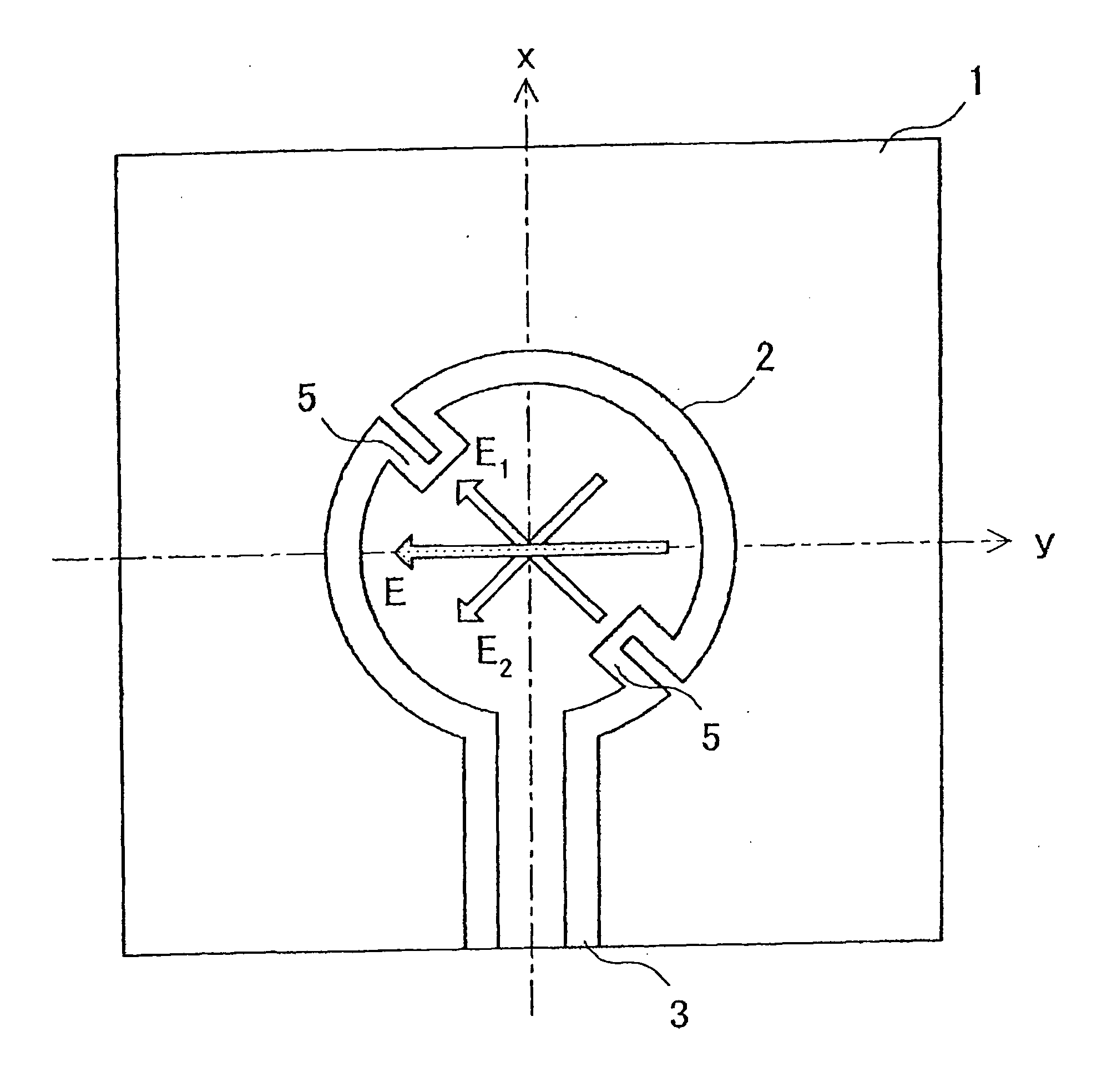
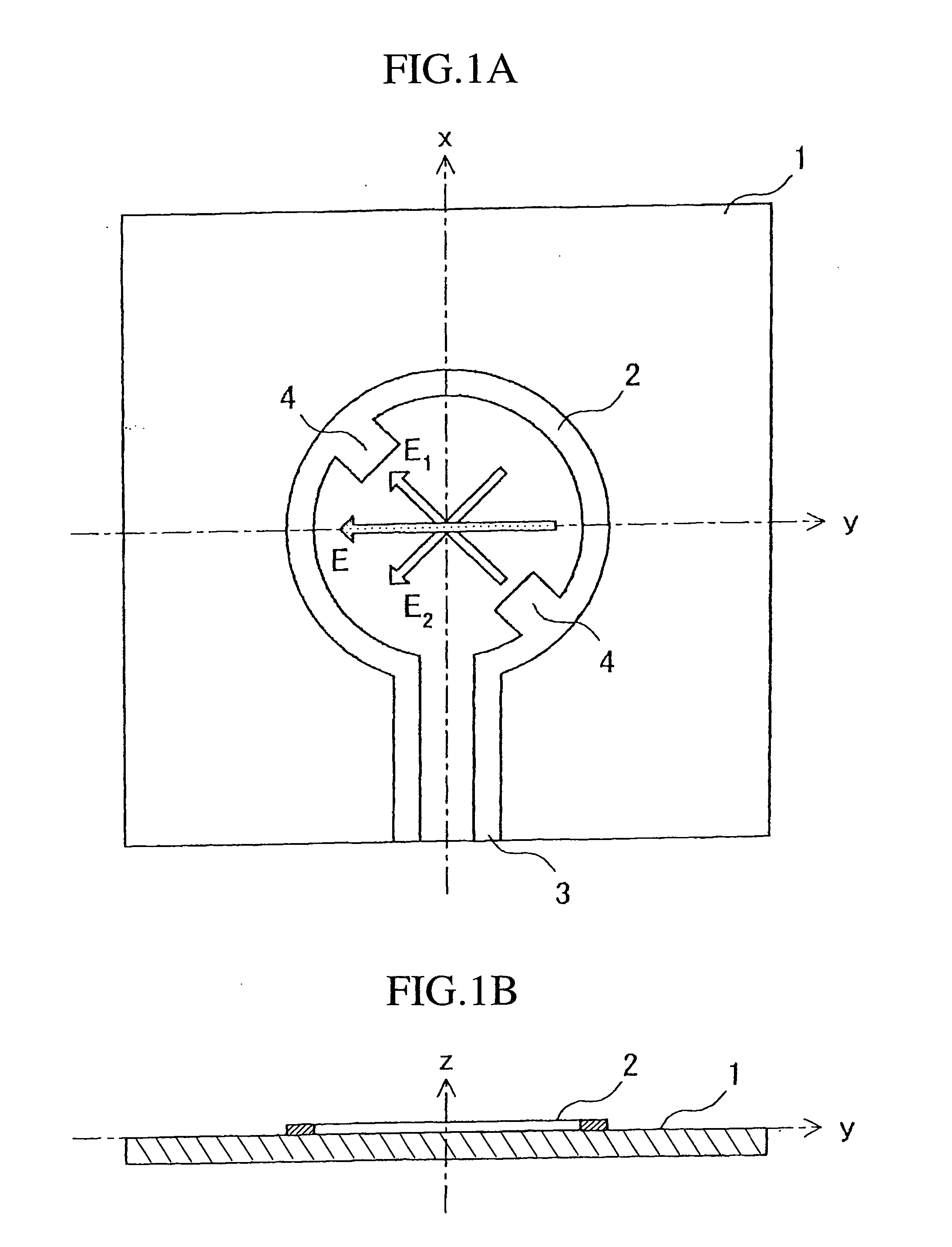
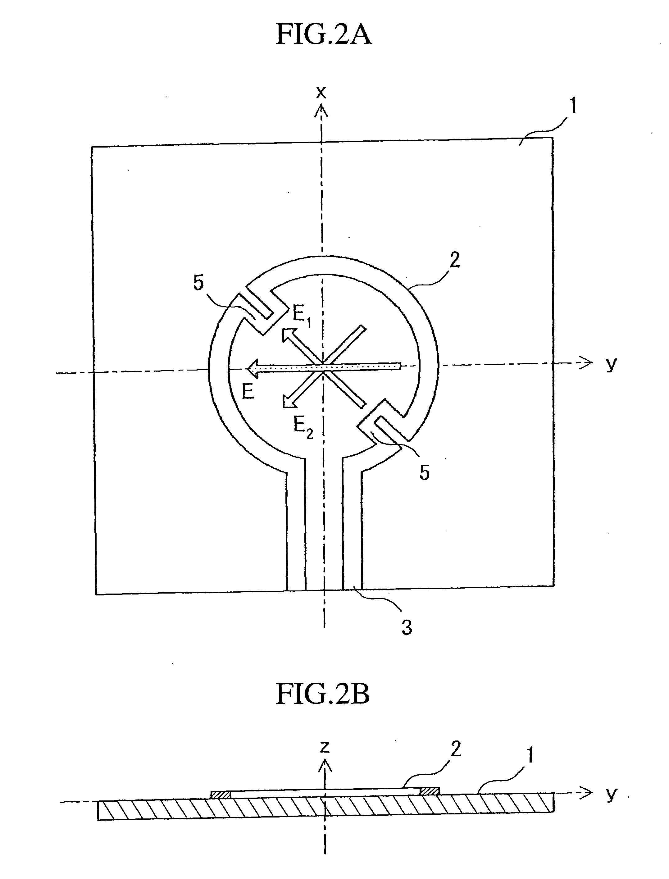
[0027] A circularly polarized antenna in accordance with embodiment 1 of the present invention will be explained with reference FIGS. 1 to 5. FIGS. 1A and 1B are views showing the structure of the circularly polarized antenna in accordance with embodiment 1 of the present invention. FIG. 1A is a front view of the circularly polarized antenna, and FIG. 1B is a cross-sectional view of the circularly polarized antenna. In FIG. 1A, reference numeral 1 denotes a dielectric board, reference numeral 2 denotes a loop antenna, reference numeral 3 denotes a balanced line, and reference numeral 4 denotes a perturbation element. The loop antenna unit 2, the balanced line 3, and two perturbation elements 4 are formed on the dielectric board 1 by using manufacturing methods, such as printing and etching. The loop antenna unit 2 is formed along the circumference of a circle, and is connected to the balanced line 3. Each of the two perturbation elements 4 is a member in the shape of a tooth which i...

embodiment 2

[0042] A rectenna element in accordance with embodiment 2 of the present invention will be explained with reference to FIGS. 6 and 7. FIG. 6 is a functional block diagram showing the functionality of the rectenna element in accordance with embodiment 2 of the present invention. In FIG. 6, reference numeral 10 denotes a microwave (i.e., RF electric power) space transmitted to the rectenna element, reference numeral 11 denotes a loop antenna unit, reference numeral 12 denotes a low pass filter (referred to as an LPF 12 from here on), reference numeral 13 denotes a rectifier circuit, reference numeral 14 denotes DC electric power outputted from the rectifier circuit 13, and reference numeral 15 denotes the rectenna element in which the loop antenna unit 11, the LPF 12, and the rectifier circuit 13 are connected in series. FIG. 7 is a diagram showing the structure of the rectenna element in accordance with embodiment 2 of present invention. As shown in FIG. 7, the loop antenna unit 11, ...

embodiment 3

[0045] A rectenna in accordance with embodiment 3 of the present invention will be explained with reference to FIGS. 8 and 9. FIG. 8 is a view showing the structure of the rectenna in accordance with embodiment 3 of the present invention. In FIG. 8, reference numeral 30 denotes a positive input terminal of a rectifier circuit of each of a plurality of rectenna elements 15, reference numeral 31 denotes a positive input terminal of the rectifier circuit of each of a plurality of rectenna elements 15, reference numeral 32 denotes a positive power feeding terminal which is disposed for feeding electric power into the plurality of rectenna elements 15, reference numeral 33 denotes a negative power feeding terminal which is also disposed for feeding electric power into the plurality of rectenna elements 15, reference numeral 34 denotes a strip line that connects the positive input terminals 30 of the plurality of rectenna elements 15 with the positive power feeding terminal 32, and refere...


PUM


Abstract

A loop antenna unit (2), a balanced line (3), and two perturbation elements (4) are formed on a dielectric board (1) by using manufacturing methods, such as printing and etching. The loop antenna unit (2) is formed along the circumference of a circle, and is connected to the balanced line (3). Each of the two perturbation elements (4) is a member in the shape of a tooth which is inclined 45 degrees against a direction of feeding of power via the balanced line (3) and which is projecting from the loop antenna unit (2) in an inward direction toward the center of the loop antenna unit (2). The two perturbation elements (4) are arranged at two opposite points in the loop antenna unit (2) so that they are opposite to each other.

Description

BACKGROUND OF THE INVENTION [0001] 1. Field of the Invention [0002] The present invention relates to a circularly polarized antenna that receives a circularly-polarized microwave transmitted thereto, and rectifies the received microwave so as to produce electric power, and a rectenna using the circularly polarized antenna. [0003] 2. Description of Related Art [0004] For example, Japanese patent application publication No. 5-110,334 discloses the structure of a prior art circularly polarized antenna element. The antenna disclosed by this patent application publication is provided with a ground conductor disposed on a back surface of a dielectric board, a ring patch antenna having perturbation elements on a surface thereof, and a power feeding conductor pattern that is so placed as not to be in contact with the ring patch antenna, and is so constructed as to supply electric power to the power feeding conductor pattern from the back side of the dielectric board. The prior art antenna e...

Claims


Application Information

Patent Timeline
Patent Type & Authority Applications(United States)
IPC IPC(8): H01Q1/24H01Q1/38H01Q7/00
CPCH01Q1/248H01Q7/00H01Q1/38
Inventor MIZUNO, TOMOHIROSATOH, HIROYUKIOKEGAWA, HIROKATSU
Owner MITSUBISHI ELECTRIC CORP
Why Eureka
Try Eureka