Liquid crystal display device

a liquid crystal display and display device technology, applied in the field of liquid crystal display, can solve the problems of the edges of moving parts are perceived as hazy by the observer, and blur injury in motion picture display, so as to prevent blur injury, prevent total image quality improvement, and prevent blur injury

Inactive Publication Date: 2005-11-24
SHARP KK
View PDF37 Cites 233 Cited by
  • Summary
  • Abstract
  • Description
  • Claims
  • Application Information

AI Technical Summary

Benefits of technology

[0073] According to the liquid crystal display device of the present invention, when the backlight is driven intermittently to prevent blur injury, the backlight illumination duration or the ratio of the image display duration in one frame period (impulse ratio) is appropriately switched in accordance with the type of the image content to be displayed or in accordance with the user's instruction, whereby it is possible to appropriately control the image quality degradation due to blur injury, stroboscopic effect, flickering and other factors, hence realize total image quality improvement.
[0074] Similarly, when blur injury is prevented by writing the black display signal into the liquid crystal display panel, the black display duration or the ratio of the image display duration in one frame period (impulse ratio) is appropriately switched in accordance with the type of the image content to be displayed or in accordance with the user's instruction, whereby it is possible to appropriately control the image quality degradation due to blur injury, stroboscopic effect, flickering and other factors, hence realize total image quality improvement.

Problems solved by technology

However, in contrast to the cathode lay tube (CRT) displays which used to be mainly adopted for these purposes, LCDs have been pointed out as a drawback which is so-called ‘blur injury’, that is, the edges of moving part are perceived to be hazy by the observer when a picture with motion is displayed.
As disclosed in, for example, Japanese Patent Application Laid-open Hei 9-325715, the cause of blur injury in motion picture display is not only attributed to the delay of the optical response time of liquid crystal, but also attributed to the LCD display method itself.
In such a hold-type display, the impulse response of image display light has a temporal spread, hence the temporal frequency characteristic lowers, which in turn causes degradation of the spatial frequency characteristic, leading to blur in the observed image.
However, reduction of the impulse ratio may induce the following problems (1) to (3).
However, when a picture without any motion blur, i.e., a content image which originally lacks smoothness in motion is displayed with a low impulse ratio, a stroboscopic defect, i.e., discrete motion of moving objects, occurs, leading to more trouble of image quality degradation.
When such an image with a small amount of motion blur is displayed with a low impulse ratio, there is a high possibility of the aforementioned stroboscopic defect occurring.
Of ocular movement, the characteristic of the following movement (movement of left and right eyes chasing a moving object approximately similarly), which is the most important characteristic for perceiving motion pictures, varies depending on the speeds of moving objects and the like, and there is a possibility that the aforementioned stroboscopic defect may occur in some image contents when the image is displayed with a low impulse ratio.
In contrast, when a target person is fixed with the background being moved, there is a high risk of image quality degradation due to occurrence of the aforementioned stroboscopic defect if the impulse ratio is set low.
However, because black display duration (non-image display duration) in one frame period increases, flicker becomes conspicuous especially in white image display areas and leads to image degradation due to flickering.
As has been described above, when the impulse ratio is set low, image quality may degrade due to occurrence of stroboscopic, flickering or other image quality defects depending on the type of image content, hence it has been difficult to achieve improvement of total image quality.
Moreover, sensitivity (dynamic visual acuity) to blur injury, stroboscopic effects and flickering greatly varies between individual users, so that it is impossible to realize improvement of total image quality for individual users.

Method used


Image

  • Liquid crystal display device
  • Liquid crystal display device
  • Liquid crystal display device

Examples


first embodiment

The First Embodiment

[0116] The first embodiment of the present invention will be hereinbelow described in detail with reference to FIGS. 8 to 10. Herein, FIG. 8 is a functional block diagram showing a fundamental schematic configuration of a liquid crystal display of the present embodiment. FIG. 9 is an illustrative view for explaining one example of a basic operating mechanism in the liquid crystal display of the present embodiment. FIG. 10 is an illustrative view for explaining another example of a basic operating mechanism in the liquid crystal display of the present embodiment.

[0117] The liquid crystal display of the present embodiment includes: as shown in FIG. 8, a demultiplexer 1 for separating images, sound data and control data (contents information, etc.,) from input multiplexed data (transport stream) made up of compression coded images in an MPEG (Moving Picture Expert Group) scheme or the like, sound data and control data and outputting these pieces of data to an image...

second embodiment

The Second Embodiment

[0151] Next, the second embodiment of the present invention will be described with reference to FIGS. 11 and 12. The same components as in the first embodiment will be allotted with the same reference numerals and their description is omitted. Here, FIG. 11 is an illustrative view for explaining one example of a basic operating mechanism in the liquid crystal display of the present embodiment, and FIG. 12 is an illustrative view for explaining another example of a basic operating mechanism in the liquid crystal display of the present embodiment.

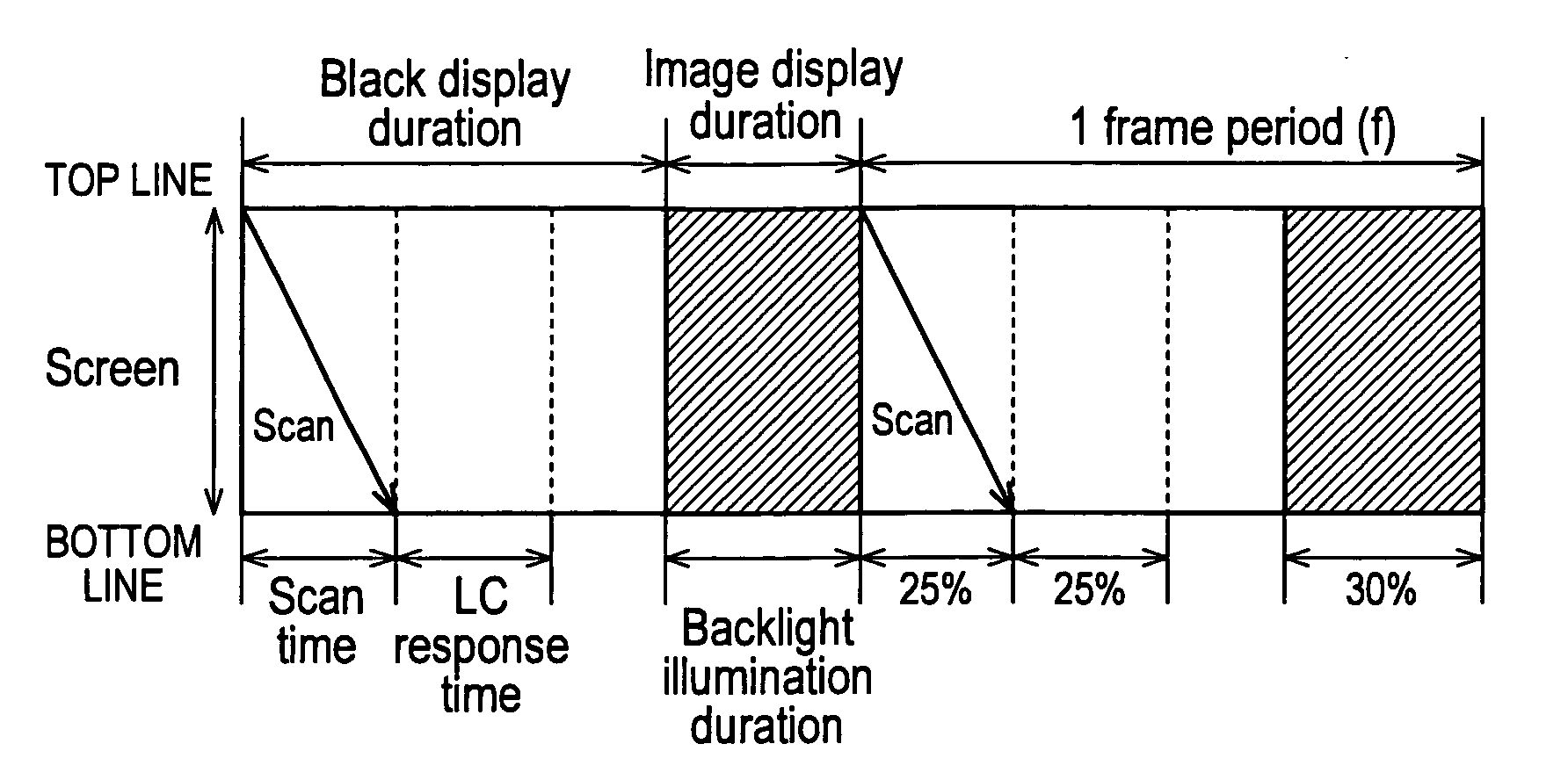
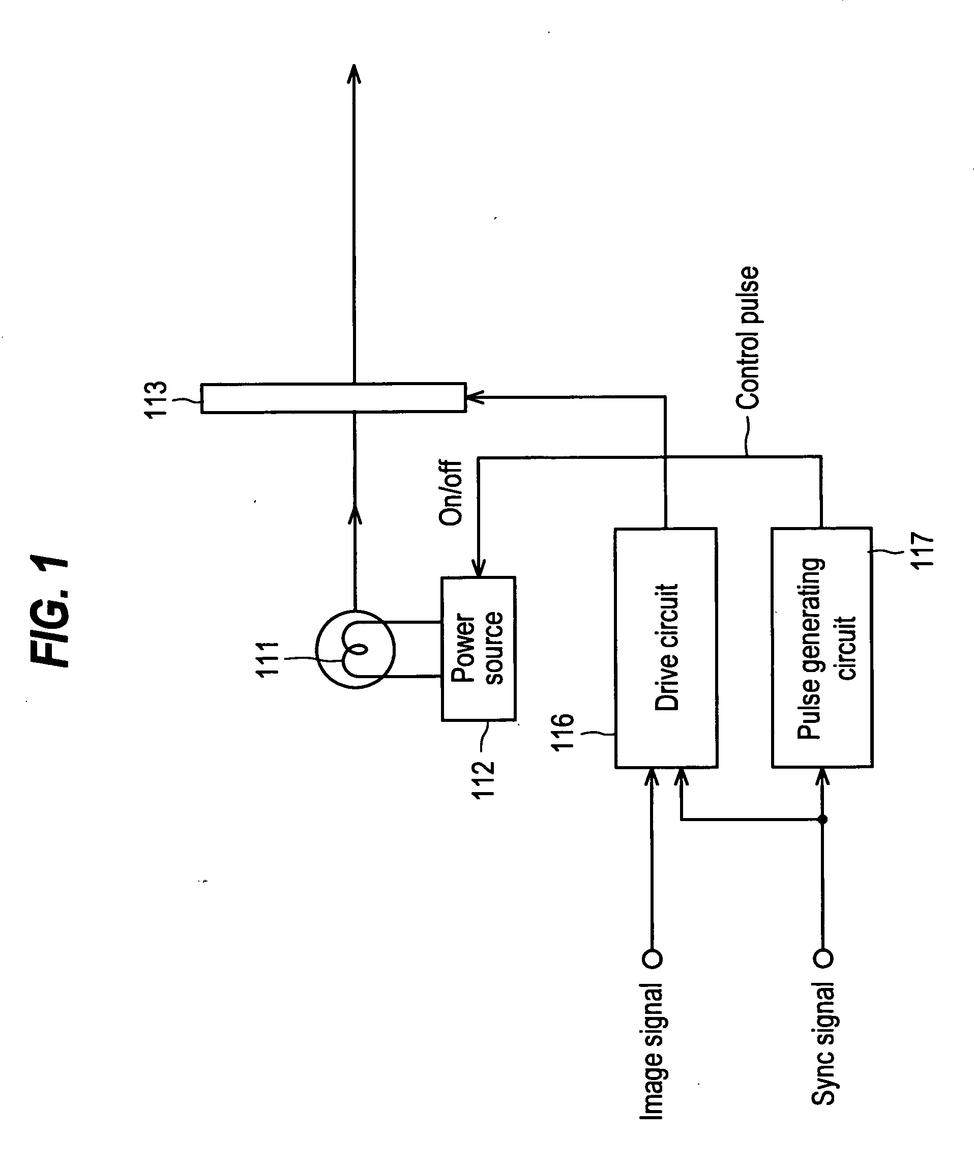
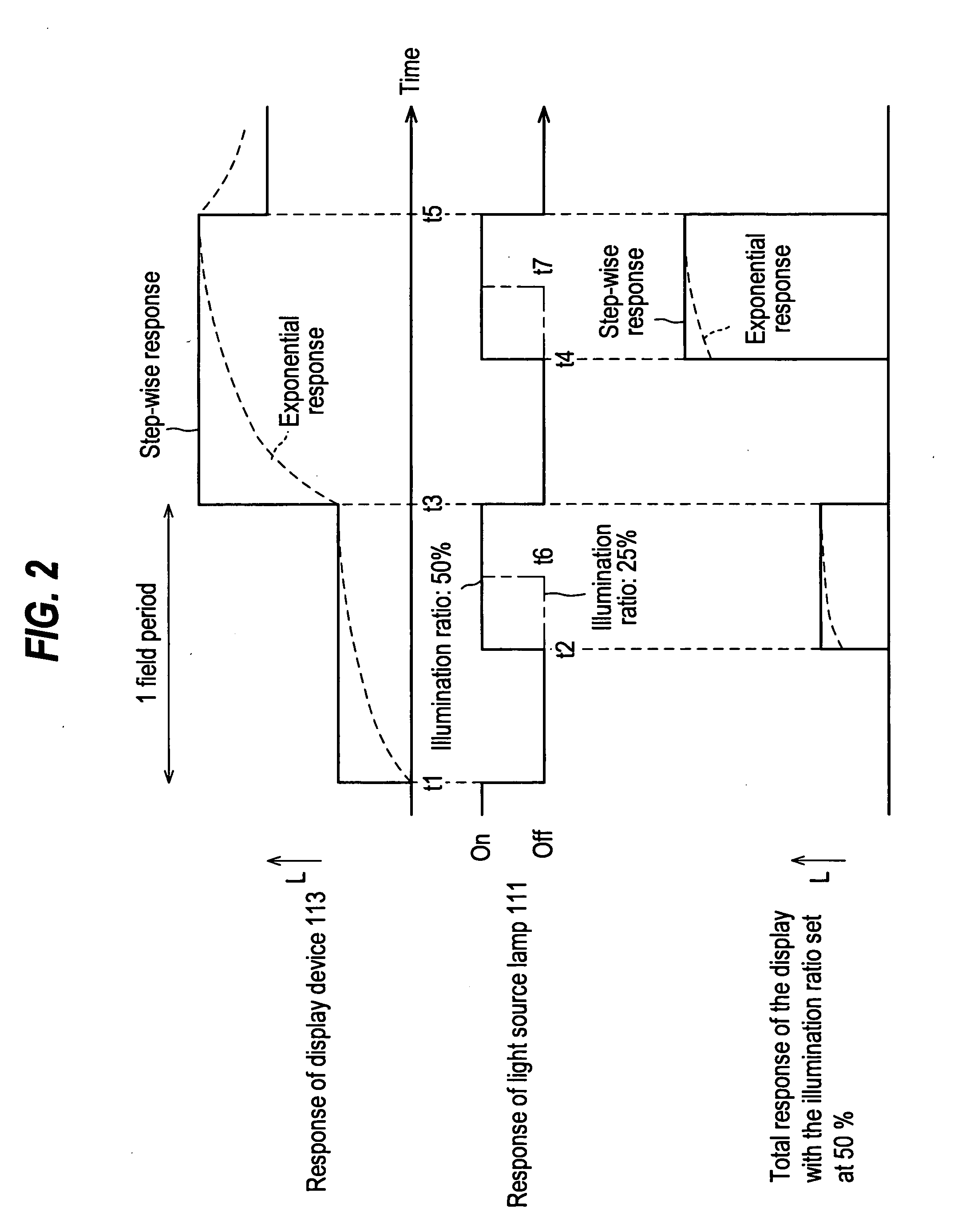
[0152] The liquid crystal display of the present embodiment is to prevent blur injury arising when displaying motion pictures, with scanning type backlight illumination, and the basic functional block diagram is much the same as the first embodiment described above with reference to FIG. 1. The difference is that a multiple number of bottom-emitting fluorescent lamps disposed parallel to the scan lines, or a multiple num...

third embodiment

The Third Embodiment

[0181] Next, the third embodiment of the present invention will be described with reference to FIGS. 13 to 15. The same components as in the second embodiment will be allotted with the same reference numerals and their description is omitted. Here, FIG. 13 is a functional block diagram showing a fundamental schematic configuration of a liquid crystal display of the present embodiment; FIG. 14 is a timing chart for explaining an electrode drive operation in a liquid crystal display of the present embodiment; and FIG. 15 is an illustrative view for explaining one example of a basic operating mechanism in a liquid crystal display of the present embodiment.

[0182] The liquid crystal display of this embodiment is to prevent blur injuries arising when displaying motion pictures by the black insertion scheme, or by writing the image display signal scan-wise and subsequently writing the black display signal scan-wise (resetting scan) into liquid crystal display panel 16 ...


PUM


Abstract

A liquid crystal display device in which a frame of the image signal to be displayed is written into a liquid crystal display panel while a backlight is activated intermittently within one frame period so as to prevent blur injury arising when displaying motion pictures includes: sections and for variably controlling the illumination duration of the backlight based on the detected type of the image content to be displayed. This configuration makes it possible to appropriately control the image quality degradation caused by blur injury, stroboscopic effect and flickering, hence realize total image quality improvement.

Description

TECHNICAL FIELD [0001] The present invention relates to a liquid crystal display for displaying images by illuminating a liquid crystal display panel with a backlight, and particularly relates to a liquid crystal display which prevents blur injury arising when displaying motion pictures, by simulating impulse type display. BACKGROUND ART [0002] Recently, flat panel type displays (FPDs) such as liquid crystal displays (LCDs) and others, which can achieve high resolution, low power consumption and space saving have been extensively developed. Among these, application of LCDs for use in computer displays, television displays and others is quite significant. However, in contrast to the cathode lay tube (CRT) displays which used to be mainly adopted for these purposes, LCDs have been pointed out as a drawback which is so-called ‘blur injury’, that is, the edges of moving part are perceived to be hazy by the observer when a picture with motion is displayed. [0003] As disclosed in, for exa...

Claims


Application Information

Patent Timeline
Patent Type & Authority Applications(United States)
IPC IPC(8): G09G3/20G09G3/34G09G3/36
CPCG09G3/2014G09G2360/144G09G3/3611G09G2310/024G09G2310/08G09G2320/0247G09G2320/0261G09G2320/0606G09G2320/062G09G2320/064G09G2320/0646G09G2320/0673G09G2320/08G09G2320/10G09G3/342G02F1/133G09G3/30
Inventor SUGINO, MICHIYUKIYOSHII, TAKASHIFUJINE, TOSHIYUKI
Owner SHARP KK
Why Eureka
Try Eureka