
Apparatus for manufacturing a vehicular lamp

Inactive Publication Date: 2005-11-24
KOITO MFG CO LTD
View PDF11 Cites 15 Cited by
  • Summary
  • Abstract
  • Description
  • Claims
  • Application Information

AI Technical Summary

Benefits of technology

[0010] It is an object of the present invention to provide an apparatus for manufacturing a vehicular lamp that joins a translucent cover and a lamp body together by means of a hot plate welding with an improved welding operation efficiency and with a minimal amount of foaming burr generated.
[0028] Accordingly, by way of providing a ceramic coat layer on the heating surface of the heating element, it is possible to allow the thermal energy of the middle infrared ray wavelength range, which is easily absorbed by the translucent cover and lamp body, to radiate to the intended welding surfaces of the translucent cover and lamp body. As a result, it is possible to further shorten the heating time.

Problems solved by technology

When the hot plate welding is performed, foaming burr unavoidably generates on both welded surfaces of the translucent cover and lamp body.
Accordingly, it takes time to heat the heating surfaces up to the proper heating temperature, and there is a problem that the welding operation efficiency is not satisfactory.
In addition, since the heating is indirectly carried out, it is not easy to precisely execute a temperature control of the heating surface.

Method used


Image

  • Apparatus for manufacturing a vehicular lamp
  • Apparatus for manufacturing a vehicular lamp
  • Apparatus for manufacturing a vehicular lamp

Examples


Embodiment Construction

[0034] Embodiments of to the present invention will be described below with reference to the accompanying drawings.

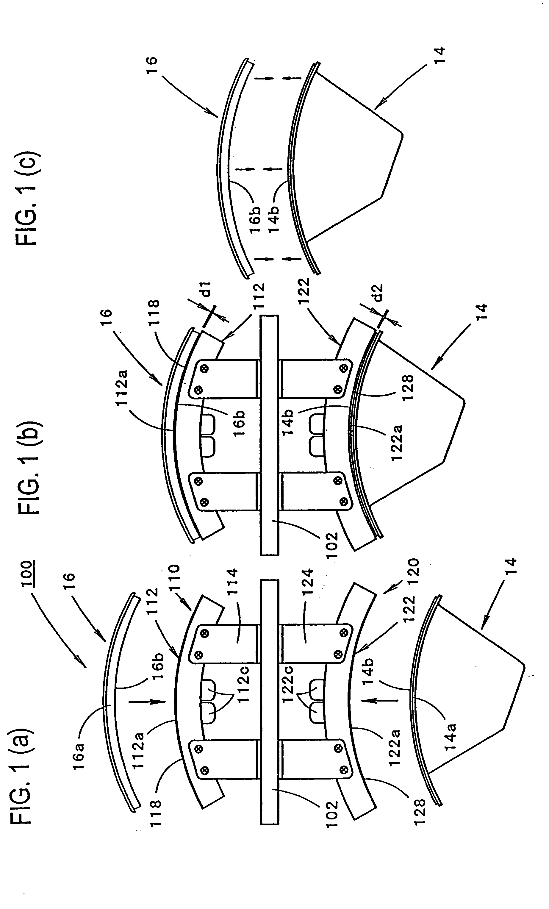
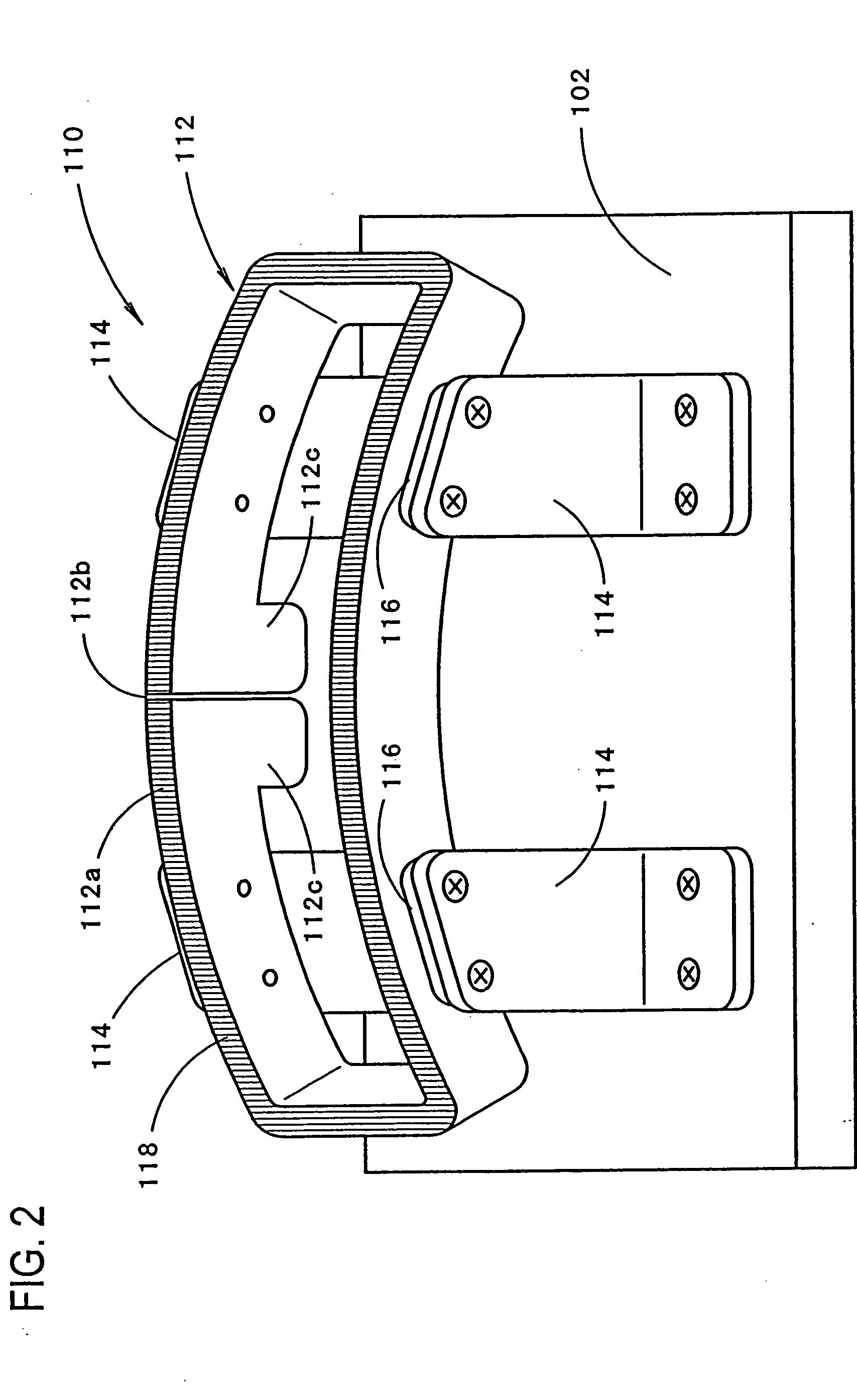
[0035] FIGS. 1(a) through 1(c) show the manufacturing process of a vehicular lamp in the manufacturing apparatus of the present invention, and FIG. 2 shows the detail of a part of the manufacturing apparatus.

[0036] Before giving a description of the manufacturing apparatus of the shown embodiment of the present invention, a description will be first made on the structure of a vehicular lamp to be manufactured.

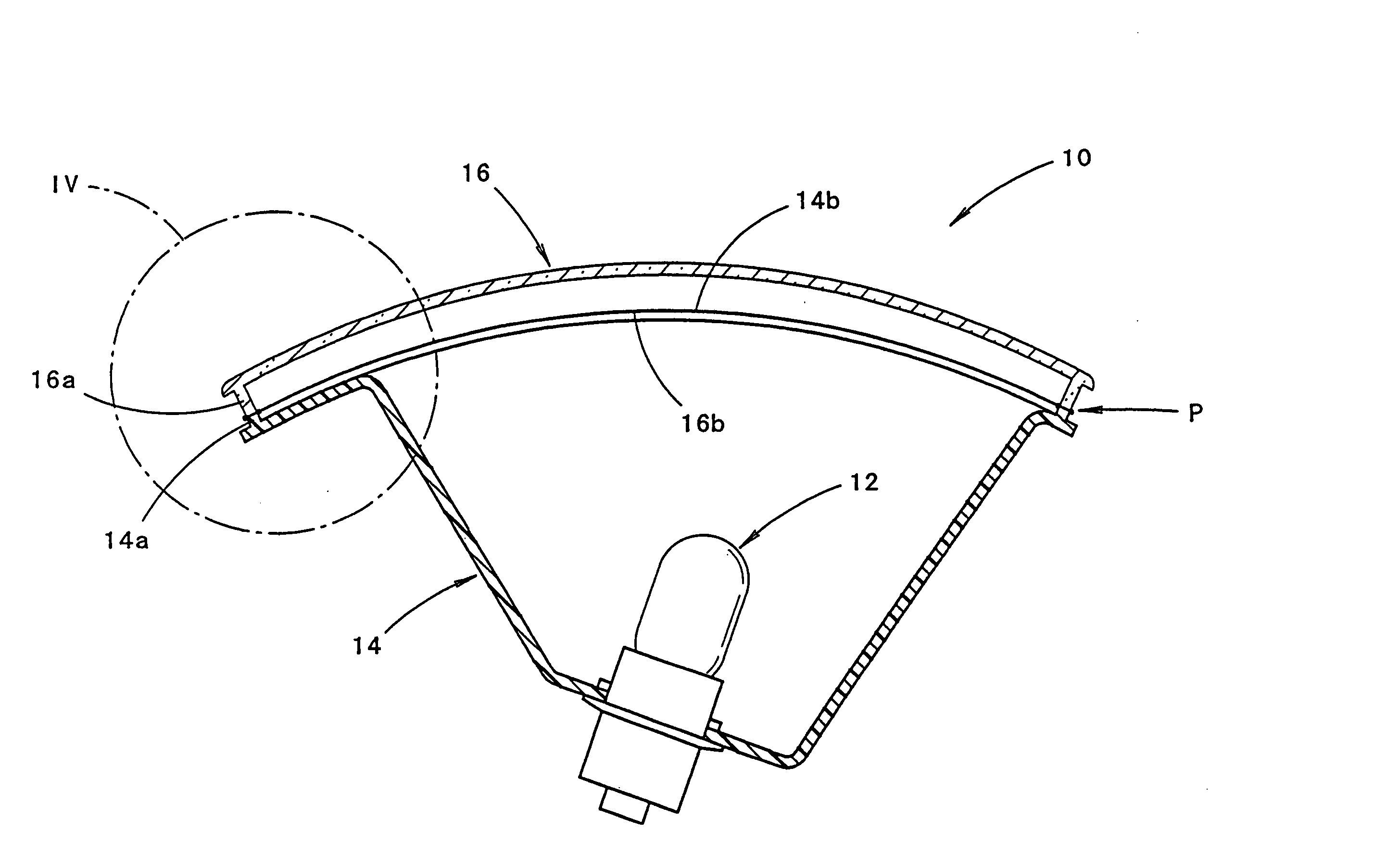
[0037]FIG. 3 shows the vehicular lamp that is manufactured by the apparatus of the shown embodiment of the present invention with the lamp set to face upward; and FIG. 4 shows the detail of one part of this lamp.

[0038] As seen from FIGS. 3 and 4, a vehicular lamp 10 to be manufactured in the shown embodiment is a marker lamp such as a tail lamp, and it is comprised of a lamp body 14, to which a light source bulb 12 is inserted and attached, and a translucent co...


PUM

PropertyMeasurementUnit
Lengthaaaaaaaaaa
Electrical resistanceaaaaaaaaaa
Shapeaaaaaaaaaa

Abstract

An apparatus for manufacturing a vehicular lamp that is formed by a lamp body and a translucent cover welded to the lamp body, the apparatus including a first heating element, which has a heating surface of substantially the same surface shape as the intended welding surface of the translucent cover and extends along the cover's intended welding surface, and a second heating element, which has a heating surface of substantially the same surface shape as the intended welding surface of the lamp body and extends along the lamp body's intended welding surface. The first and second heating elements are made of a resistance heating material.

Description

BACKGROUND OF THE INVENTION [0001] 1. Field of the Invention [0002] The present invention relates to an apparatus for manufacturing a vehicular lamp that welds a translucent cover and a lamp body together by a so-called hot plate welding. [0003] 2. Prior Art [0004] Conventionally, hot plate welding has been used for welding a translucent cover and a lamp body of a vehicular lamp. [0005] In the hot plate welding described in, for instance, Japanese Patent Application Laid-Open (Kokai) No. 2001-297608, a translucent cover and a lamp body are welded by first heating the intended welding surfaces of the translucent cover and lamp body of a vehicle using a heating element and then pressing the intended welding surfaces to each other. In this hot plate welding, the heating element is structured such that a cartridge that serves as a heat source is buried in a block-shaped metal member having a heating surface of substantially the same surface shape as the intended welding surfaces of the ...

Claims


Application Information

Patent Timeline
IPC IPC(8): B29C35/08F21S8/10B29C65/00B29C65/14B29C65/20B29C65/30B29L22/00F21V5/00F21V17/00
CPCB29C65/1412B29C66/542B29C65/1432B29C65/1467B29C65/20B29C65/2015B29C66/1142B29C66/131B29C66/24B29C66/301B29C66/324B29C66/91421B29C66/919B29C66/949B29C2035/0822B29K2033/12B29K2055/02B29K2069/00B29K2101/12B29K2905/12B29K2909/02B29K2995/0029B29L2031/30B29L2031/747B29C65/1419B29C65/1416B29C65/00B29C66/83221B29C66/81422B29C66/81423B29C66/73921B29C66/24244B29C66/8122B29C66/71B29C66/712B29K2025/08
Inventor NISHIZAKI, MASAHIKOOTANI, HARUOSUGIYAMA, FUJIHIKOYAMAZAKI, KAZUHIRO
Owner KOITO MFG CO LTD
Features
  • Generate Ideas
  • Intellectual Property
  • Life Sciences
  • Materials
  • Tech Scout
  • Unparalleled Data Quality
  • Higher Quality Content
  • 60% Fewer Hallucinations
Learn More