Vortex-flow air removal in a blood perfusion system

a blood perfusion system and vacuum technology, applied in the field of vacuum air removal in the blood perfusion system, can solve the problems of inability to use when active drainage is desired, fvr will not work during active drainage, fvr to collapse, etc., and achieve the effect of efficient air removal, minimal exposure of blood to a defoamer, and low prime volum

Inactive Publication Date: 2005-11-24
TERUMO CARDIOVASCULAR SYST CORP
View PDF13 Cites 17 Cited by
  • Summary
  • Abstract
  • Description
  • Claims
  • Application Information

AI Technical Summary

Benefits of technology

[0008] The present invention provides an air removal device and method with low prime volume, efficient air removal, and minimal exposure of blood to a defoamer. The device described herein does not collapse under negative pressure and can be used in place of a cardiotomy reservoir for both passive and active drainage procedures.

Problems solved by technology

An FVR will not work during active drainage because the negative pressure in the circuit will cause the FVR to collapse.
Since an FVR provides a closed system (i.e., not open to atmosphere) it can achieve some of these advantages to a certain degree, but it cannot be used when active drainage is desired because of the tendency to collapse under negative pressure.
Cost and potential reliability issues associated with active sensing and purging are disadvantageous.

Method used


Image

  • Vortex-flow air removal in a blood perfusion system
  • Vortex-flow air removal in a blood perfusion system
  • Vortex-flow air removal in a blood perfusion system

Examples


Embodiment Construction

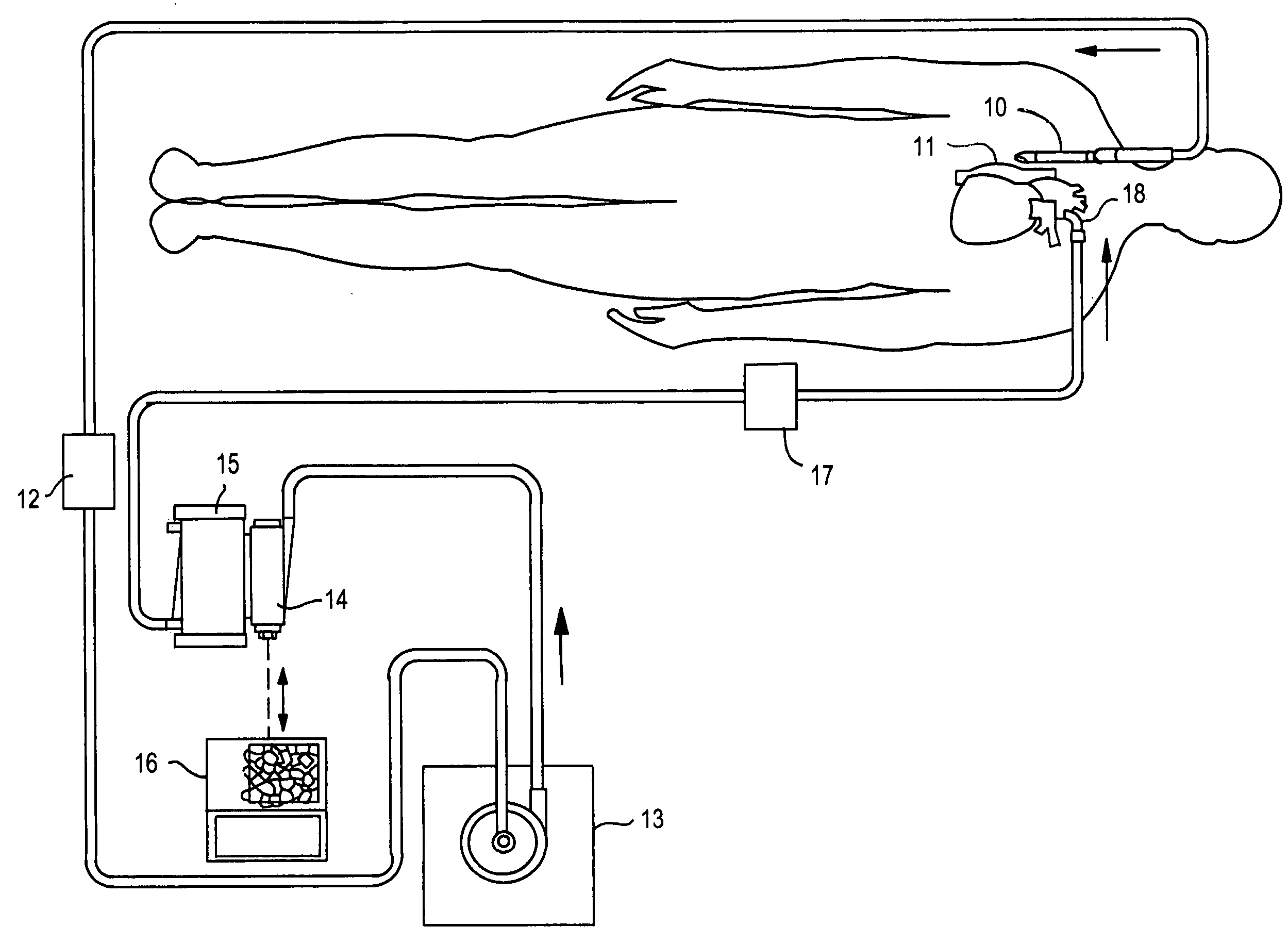
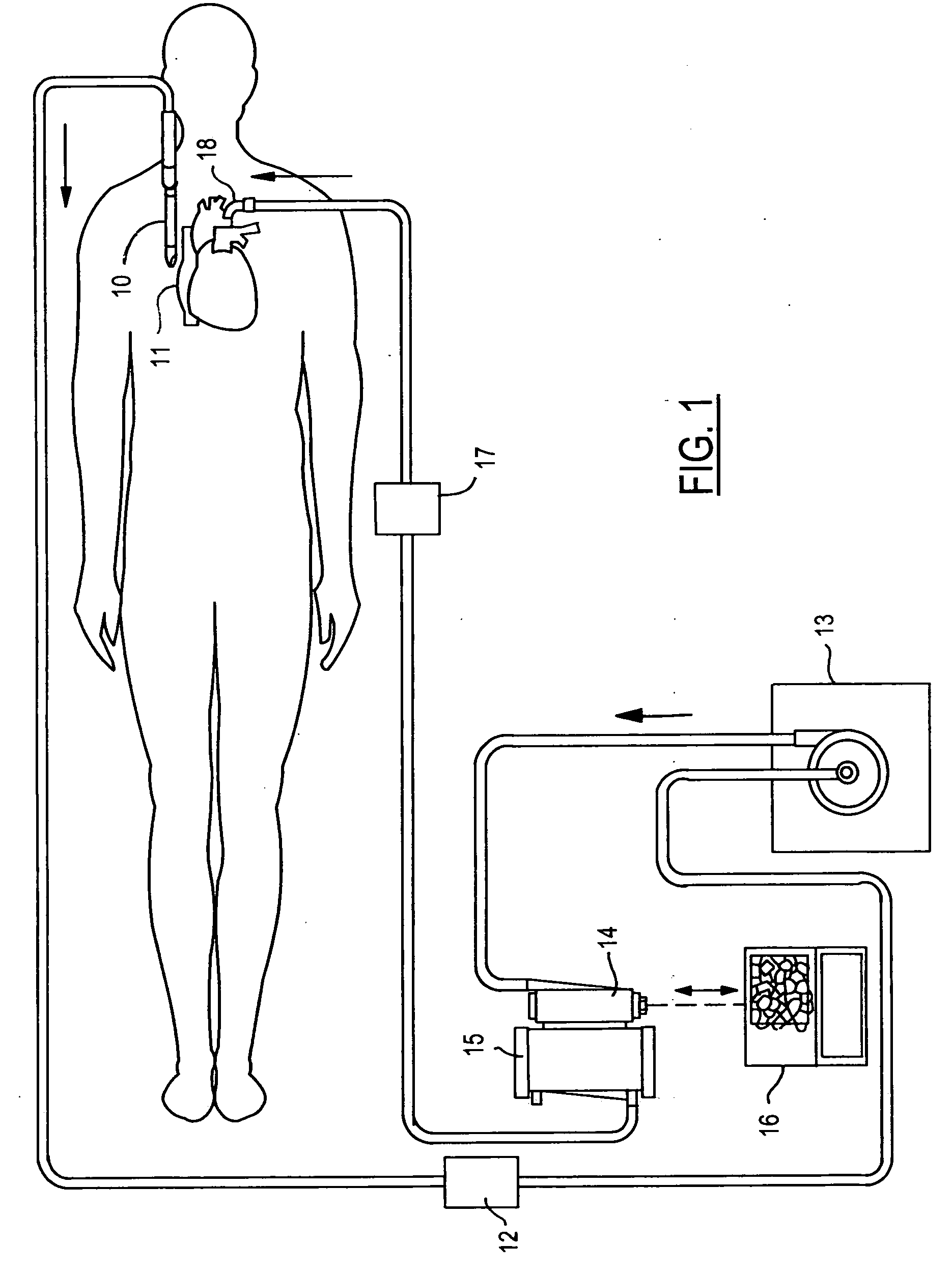
[0023]FIG. 1 shows a simplified diagram of a perfusion system for supporting on-pump coronary artery bypass graft surgery. A venous catheter 10 is inserted at 11 into the right side of a patient's heart or the superior or inferior vena cava. Venous blood flow is driven by an arterial pump 13 which may be comprised of a centrifugal pump, for example. Blood passes through a heat exchanger 14 and then to an oxygenator 15. A blood heater / cooler 16 is connected to heat exchanger at 14 for selectably heating or cooling blood as is required during different phases of surgery. Oxygenated blood is conducted to an arterial cannula 18 to return the oxygenated blood to the patient's aorta.

[0024] Air in the form of a bolus or bubbles can be introduced into the blood at the point of extraction from the body due to a leak around the venous catheter, for example. It is desirable to remove entrained air prior to the blood entering the pump and oxygenator. Thus, an air removal device 12 is preferabl...


PUM


Abstract

An air removal system removes air from blood flowing in a perfusion system. A first elongated, substantially cylindrical chamber is provided having a central longitudinal axis between an upstream end and a downstream end, wherein the chamber provides a substantially unobstructed blood flow path therethrough along a wall of the chamber, and wherein the downstream end provides an air-reduced blood flow to the perfusion system. A vortex flow introducer is located substantially at the upstream end. A bubble stop is provided which blocks the central longitudinal axis prior to the downstream end. An air removal line is coupled to the central longitudinal axis between the upstream end and the bubble stop. An air extraction unit has an input coupled to the air removal line, an air output for coupling to a vacuum source via a valve, and a blood output. A blood return line is coupled to the blood output for returning blood passing through the air extraction unit to a return point that is downstream of the bubble stop.

Description

CROSS REFERENCE TO RELATED APPLICATIONS [0001] This application claims priority to co-pending U.S. provisional application Ser. No. 60 / 573,923, filed May 24, 2004.STATEMENT REGARDING FEDERALLY SPONSORED RESEARCH [0002] Not Applicable. BACKGROUND OF THE INVENTION [0003] The present invention relates in general to extracorporeal blood perfusion systems, and, more specifically, to an air removal system and device for separating entrained air from blood flowing in the system. [0004] When heart surgery is performed ‘on pump’, steps are taken to remove air entrained in the blood flowing in the extracorporeal blood circuit. Preferably, air removal occurs upstream of the pump. Typically, either a cardiotomy reservoir with defoamer or a flexible venous reservoir (FVR) has been employed. An FVR typically comprises a sealed bag with a luer valve or stopcock at its upper end for manually removing excess air. A cardiotomy reservoir comprises a hard shell for collecting and storing blood which is...

Claims


Application Information

Patent Timeline
Patent Type & Authority Applications(United States)
IPC IPC(8): A61M1/36A61M27/00A61M37/00
CPCA61M1/3627A61M2206/16A61M2025/0031A61M27/00A61M1/3606A61M1/3623
Inventor GAY, ERIC L.
Owner TERUMO CARDIOVASCULAR SYST CORP
Why Eureka
Try Eureka