Conformal vacuum cup apparatus and method

a vacuum cup and apparatus technology, applied in the field of uniform vacuum cup apparatus and method, can solve the problems of system to the fuselage, fore-and-aft along a curving wing rib, prone to uncertainty, and unable to conform smoothly to severe contours

Active Publication Date: 2005-12-01
THE BOEING CO
View PDF11 Cites 33 Cited by
  • Summary
  • Abstract
  • Description
  • Claims
  • Application Information

AI Technical Summary

Benefits of technology

[0009] In still another aspect, an attachment between a rail with a longitudinal axis and a rail-side surface of the workpiece comprises means for stiffening a vacuum cup along an axis transverse to the longitudinal axis of the rail and parallel to the rail-side surface of the workpiece, means for removably sealing the stiffening means to the rail-side surface of the workpiece against vacuum loss, means for rigidly positioning a point on the rail with respect to a point on the rail-side surface of the workpiece, and means for coupling a vacuum source to a spatial volume occupying all of a space between the means for sealing and the rail-side surface of the workpiece.
[0010] In yet another aspect, a method for removably attaching a rail with a longitudinal axis to a rail-side surface of a workpiece comprises stiffening a vacuum cup along an axis transverse to the longitudinal axis of the rail and parallel to the rail-side surface of the workpiece, removably sealing a perimeter of the vacuum cup to the rail-side surface of the workpiece against vacuum loss, rigidly positioning a point on the rail with respect to a point on the rail-side surface of the workpiece, and coupling a vacuum source to a spatial volume occupying all of a space between the vacuum cup and the rail-side surface of the workpiece.

Problems solved by technology

For example, some prior art vacuum cup systems could be attached readily along the flight direction of a cylindrical or otherwise highly curved fuselage, particularly where the fuselage has a long, essentially straight extent (i.e., a contour near zero), but attaching such a system to the fuselage in the circumferential direction, or fore-and-aft along a curving wing rib, would tend sometimes to produce uncertain results.
Prior art systems that use small numbers of large vacuum cups have been used, but have tended to be unable to conform smoothly to severe contours.
Prior art systems with large numbers of small vacuum cups can follow a contour to some extent, but tend to be limited in the available retaining force by the necessity of having physical clearance around each vacuum cup, and by the limited available length-to-width ratio of an individual cup.
Nonetheless, prior art systems tend to be limited in their ability to conform to generalized surfaces, being best suited to positioning along low-contour paths.

Method used


Image

  • Conformal vacuum cup apparatus and method
  • Conformal vacuum cup apparatus and method
  • Conformal vacuum cup apparatus and method

Examples


Embodiment Construction

[0025] Various embodiments in accordance with the present invention provide vacuum cup apparatus and methods for attachment of devices such as, for example, a rail system used in operations such as drilling series of holes, which holes may be needed for assembling screws or rivets through airplane sheet surfaces into underlying structures. Although described in the context of aircraft manufacturing, various embodiments can also be useful in other manufacturing industries. The invention will now be described with reference to the drawing figures, in which like reference numerals refer to like parts throughout.

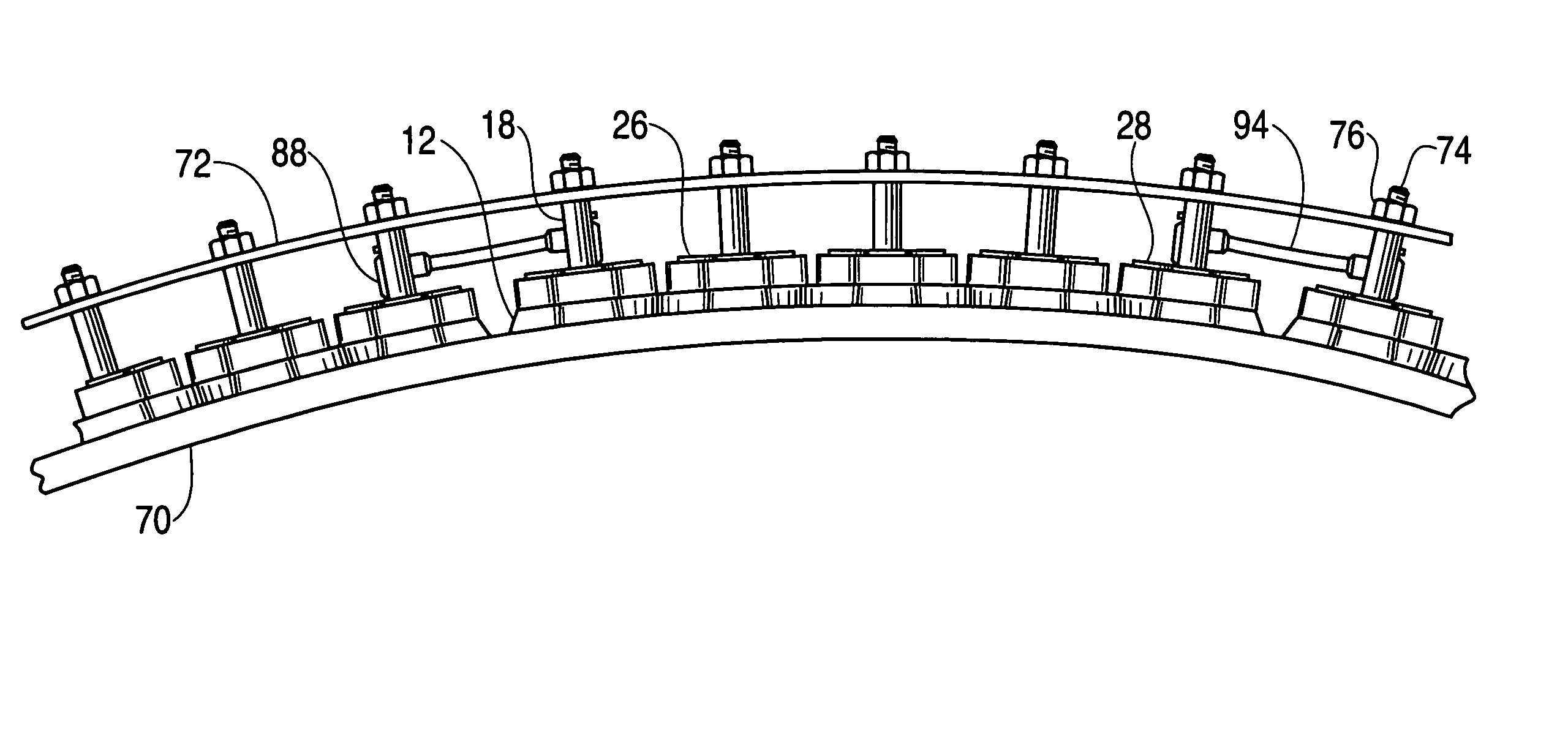
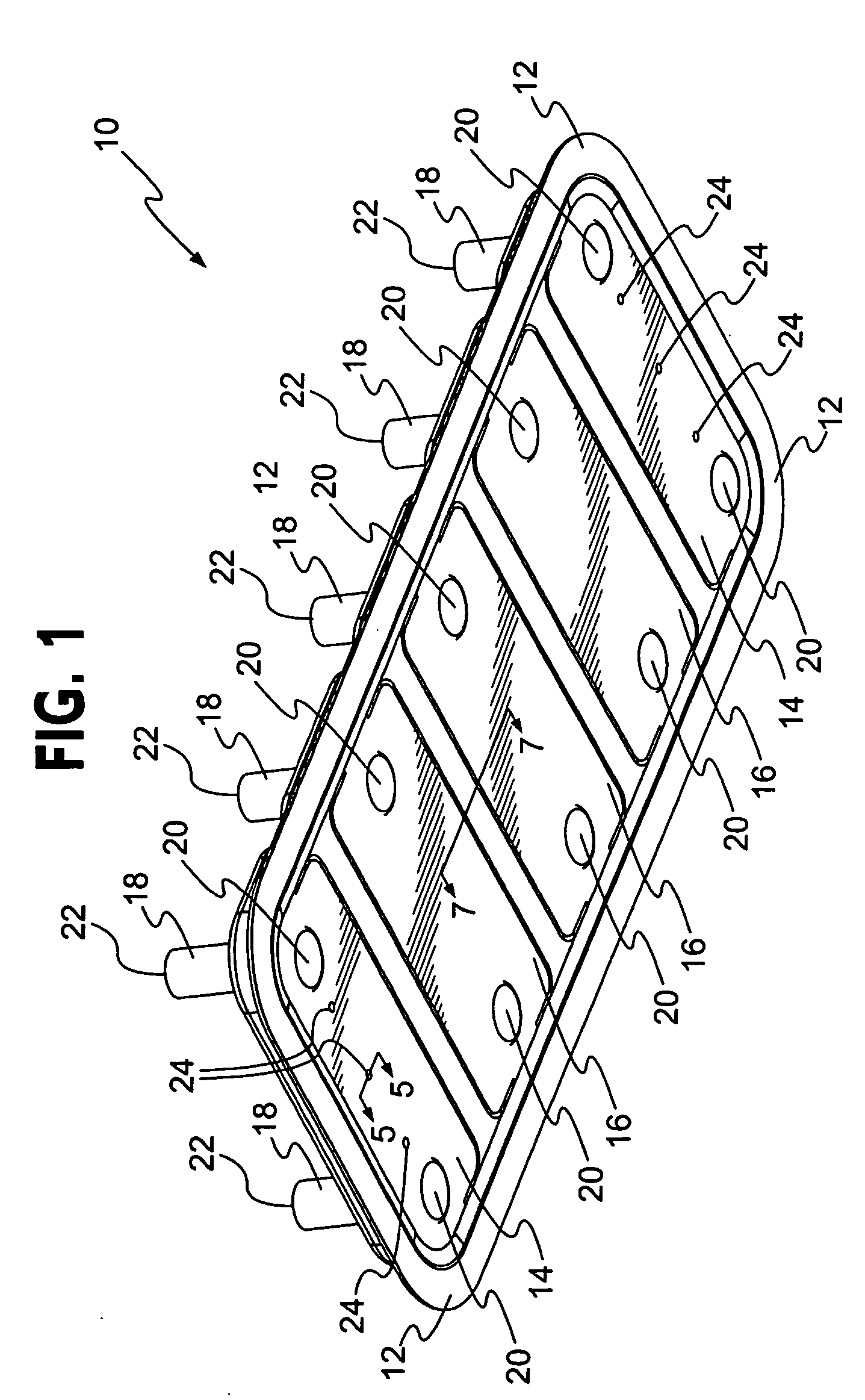
[0026]FIG. 1 is an oblique bottom view that shows a fully compressed vacuum cup 10 according to an exemplary embodiment. The vacuum cup 10 has a peripheral sealing lip 12 that is shown deflected as it would be seen from below a transparent workpiece (a workpiece 70 is shown in FIGS. 7 and 11) when vacuum from an external vacuum system (shown in FIG. 10) has been applied to the ...


PUM

PropertyMeasurementUnit
areaaaaaaaaaaa
flexibleaaaaaaaaaa
volumeaaaaaaaaaa

Abstract

A conformal vacuum cup provides a machine tool attachment fitting usable in a flexible-track drill system. Using multiple, independently articulated stiffeners, the conformal vacuum cup conforms to the contour of complex aerostructure surface shapes. The individual stiffeners are decoupled from each other to some extent by grooves and slots molded into resilient overmolding material to support long-axis curving. Spacing pins employ a domed shape consonant with the elastic deformation of the workpiece surface under load. The pins employ a hard material to prevent particle embedment in use and to control position tolerance for drill heads and other tools traveling on the flexible track. Partial holes in each vacuum cup are blocked by diaphragms. Interconnection from a vacuum system manifold to the vacuum cups can be realized by penetrating the diaphragms and inserting barbed fittings connected by vacuum tubing.

Description

FIELD OF THE INVENTION [0001] The present invention relates generally to manufacturing tools and automation. More particularly, the present invention relates to attachment of rail-mounted machine tools to work surfaces. BACKGROUND OF THE INVENTION [0002] Portable, vacuum-cup-attached systems for drilling or fastening sections of aircraft fuselage or wing structures, as well as for other manufacturing operations, for other vehicle types, and for static structures, have been developed previously, but have generally been most practical for use only on workpiece areas where the contour is zero or very small in the longitudinal direction of the device. For example, some prior art vacuum cup systems could be attached readily along the flight direction of a cylindrical or otherwise highly curved fuselage, particularly where the fuselage has a long, essentially straight extent (i.e., a contour near zero), but attaching such a system to the fuselage in the circumferential direction, or fore-...

Claims


Application Information

Patent Timeline
Patent Type & Authority Applications(United States)
IPC IPC(8): B25B5/16B25B11/00
CPCB25B11/007Y10T29/49956Y10T29/53191Y10T29/5191Y10T408/55Y10T29/49622Y10T29/49998Y10T409/30644Y10T29/5108Y10T29/5118B23Q2210/008B25B11/00B64C3/00
Inventor BOYL-DAVIS, THEODORE M.BUTTRICK, JAMES N. JR.JONES, DARRELL D.
Owner THE BOEING CO
Why Eureka
Try Eureka