
Car power source apparatus

a technology for power sources and cars, applied in the field of car power sources, can solve the problems of difficult to obtain sufficient output from the driving battery, low temperature of the driving battery, etc., and achieve the effect of reducing load and large load on the driving battery

Active Publication Date: 2005-12-01
SANYO ELECTRIC CO LTD
View PDF3 Cites 64 Cited by
  • Summary
  • Abstract
  • Description
  • Claims
  • Application Information

AI Technical Summary

Benefits of technology

[0007] The present invention was developed to solve these problems. Thus it is an object of the present invention to provide a car power source apparatus which can heat the driving battery when external and surrounding temperatures are low, and while preventing driving battery over-discharge.
[0010] In the car power source apparatus described above, when the car is not being driven and the driving battery is heated by the heaters with electric power from the driving battery, the set temperature is changed In the control circuit to correspond to the detected surrounding temperature. Further, the set temperature is equal to 0 to 15° C. added to the detected surrounding temperature. Since a conventional apparatus heats to a pre-set temperature independent of the surrounding temperature, a large amount of electric power is required, and the load on the driving battery is large. However, in the apparatus described above, the set temperature is changed according to the surrounding temperature to a value which is 0 to 15° C. added to the surrounding temperature. Therefore, large amounts of electric power are not demanded from the driving battery and its load is reduced.

Problems solved by technology

Consequently, when external temperature is low and the car is driven after having the ignition switch in the off state, driving battery temperature is low and it is difficult to obtain sufficient output from the driving battery.

Method used


Image

  • Car power source apparatus
  • Car power source apparatus
  • Car power source apparatus

Examples


Embodiment Construction

[0023] First, the structure of embodiments of power source apparatus of the present invention are described using FIGS. 1-9. Next, electric circuitry is described using the circuit embodiment of the block diagram shown in FIG. 10.

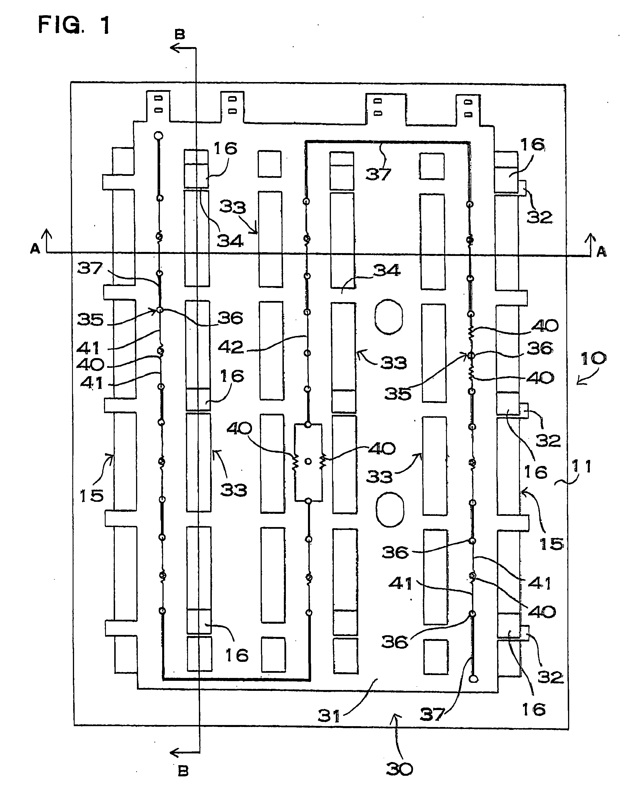
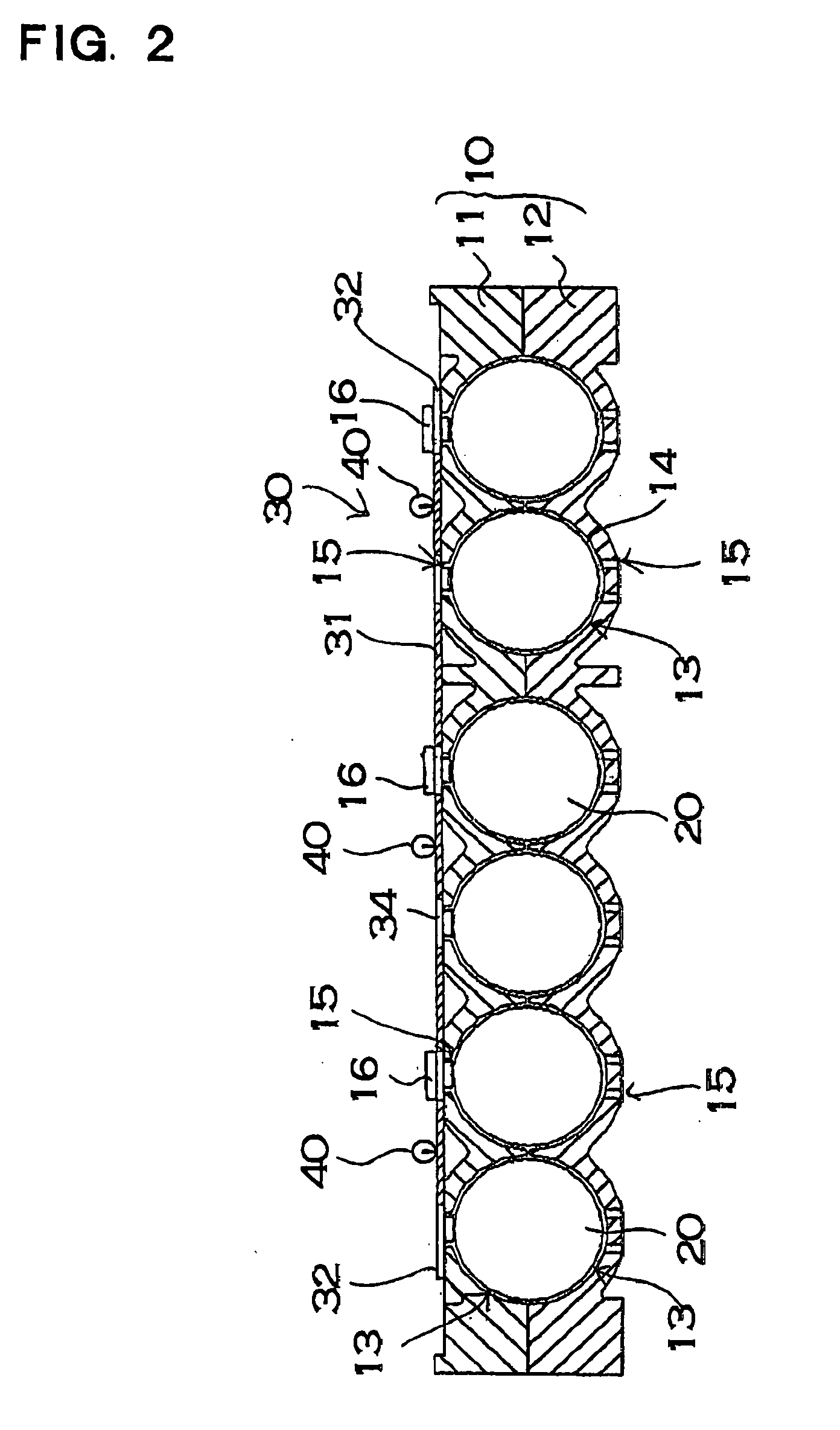
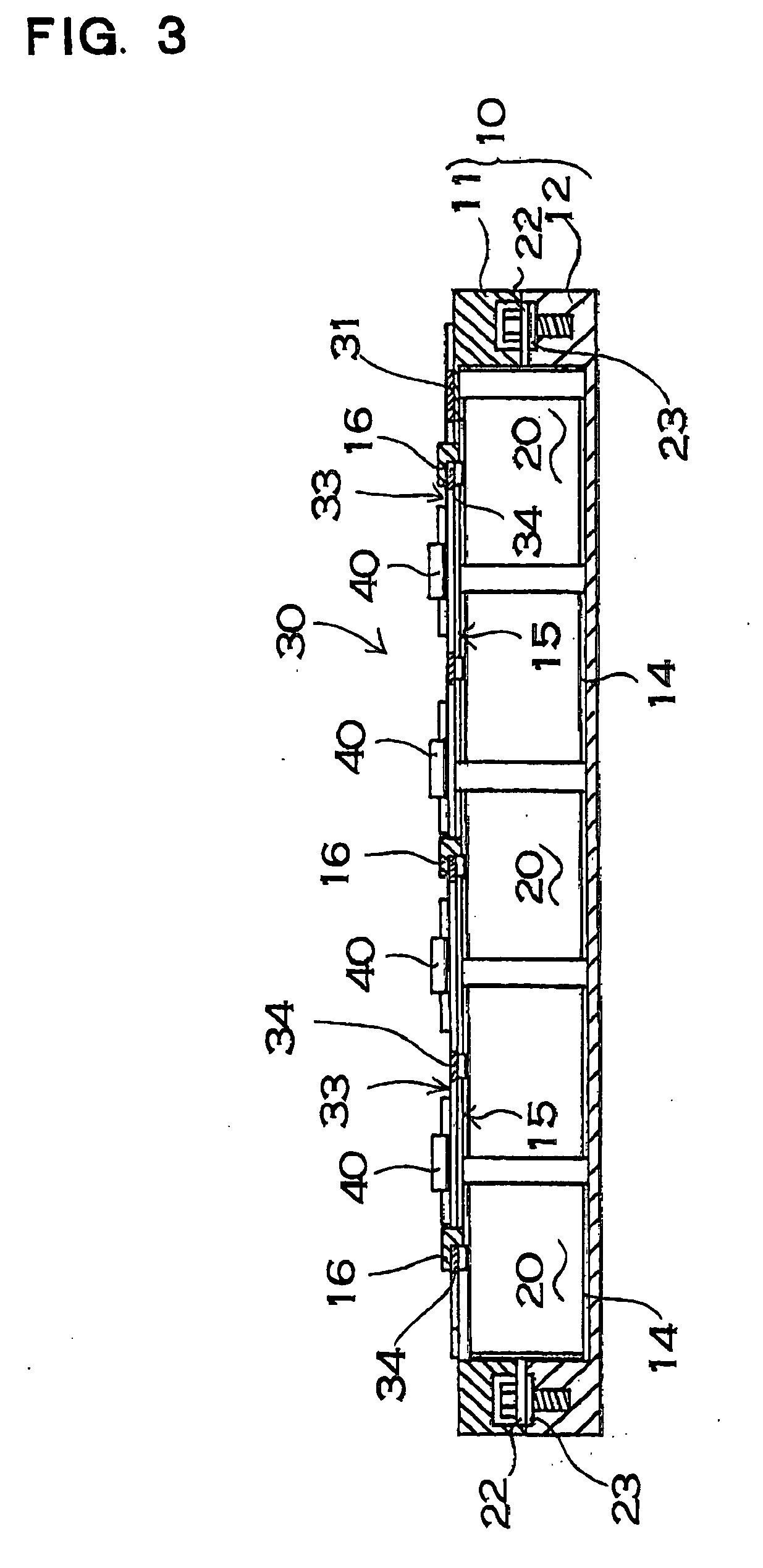
[0024] FIGS. 14 show an embodiment of a car power source apparatus of the present invention. FIG. 1 is a plan view, FIG. 2 is a lateral cross-section view, FIG. 3 is a vertical cross-section view, and FIG. 4 is a plan view showing the case 10 open. This power source apparatus has a plurality of rechargeable batteries 20 arranged inside a case 10. The power source apparatus has a plurality of rechargeable batteries 20 separated into modules 21 and housed in the case 10. A battery module 21 is a plurality of series connected rechargeable batteries 20 joined in a straight-line fashion. Rechargeable batteries 20 which make up a battery module 21 are circular cylindrical nickel hydrogen batteries. However, other batteries which can be recharged, such as lithium...


PUM


Abstract

The car power source apparatus is provided with a driving battery which drives an electric motor, heaters which heat the driving battery, a control circuit which controls power to the heaters, a temperature sensor which detects battery temperature and issues a detected temperature signal to the control circuit, and a surrounding temperature sensor which detects surrounding temperature and also issues a detected temperature signal to the control circuit. When the car is not being driven and the driving battery is heated via the heaters powered by the driving battery, the set temperature is changed corresponding to the detected surrounding temperature in the control circuit.

Description

BACKGROUND OF THE INVENTION [0001] 1. Field of the Invention [0002] This invention relates to a car power source apparatus provided with heaters to increase the temperature of the driving battery that powers the electric drive motor of a vehicle, such as an automobile, when temperatures are low. [0003] 2. Background Art [0004] When temperatures become extremely low, battery output decreases and sufficient performance cannot be obtained. Consequently, when a hybrid car is used in a frigid location and the temperature of the driving battery becomes low, sufficient battery performance cannot be output when beginning to move or accelerate the car. A hybrid car is designed to normally run on both an engine and an electric motor. If performance of the driving battery decreases and power from the motor is insufficient, the hybrid car cannot operate normally. This drawback can be resolved by warming-up (heating) the battery. To realize this, the present applicant developed a power source ap...

Claims


Application Information

Patent Timeline
IPC IPC(8): B60R16/04B60K1/04B60L3/00B60L11/18B60L50/15H01M10/60H01M10/615H01M10/625H01M10/633H01M10/635H01M10/643H01M10/6554H01M10/6561H01M10/6563H01M10/6565H01M10/6566H01M10/6571H02J7/00
CPCB60L1/10B60L11/123B60L11/1851B60L11/187B60L11/1875B60W2510/246Y10S903/907Y02T10/6217Y02T10/7005Y02T10/705Y02T10/7077Y02T10/90H01M10/5006B60W2510/244B60L50/61B60L58/10B60L58/24B60L58/27H01M10/615Y02E60/10Y02T10/62Y02T10/70Y02T10/7072
Inventor INUI, SHINYA
Owner SANYO ELECTRIC CO LTD
Learn More