Organic electro luminescence display device and driving method thereof

Active Publication Date: 2005-12-01
LG DISPLAY CO LTD
View PDF35 Cites 35 Cited by
  • Summary
  • Abstract
  • Description
  • Claims
  • Application Information

AI Technical Summary

Benefits of technology

[0019] Accordingly, it is an object of the present invention to provide an organic electro luminescence display device that t

Problems solved by technology

The PDP is relatively simple in its structure and fabricating process, thus it is most advantageous in being made into large screen, but there is a big disadvantage in that its luminous efficiency and brightness is low and its power consumption is high.
However, the LCD is fabricated by a semiconductor process, thus there is difficulty in being made into large screen.
And, the LCD is not a self luminous device to require a separate light source, thus there is a disadvantage in that its power consumption is high due to the light source.
Further, the LCD has a disadvantage in that its viewing angle is narrow and light loss is great due to optical devices such as a polarizing sheet, a prism sheet, a diffusion plate and etc.
The organic EL elements OLED of the organic EL display device are charged with the current for a response time RT which is delayed by resistance components of the data lines D1 to D3 and a capacitance which is in the organic EL elements OLED, thus there is a problem i

Method used


Image

  • Organic electro luminescence display device and driving method thereof
  • Organic electro luminescence display device and driving method thereof
  • Organic electro luminescence display device and driving method thereof

Examples


first embodiment

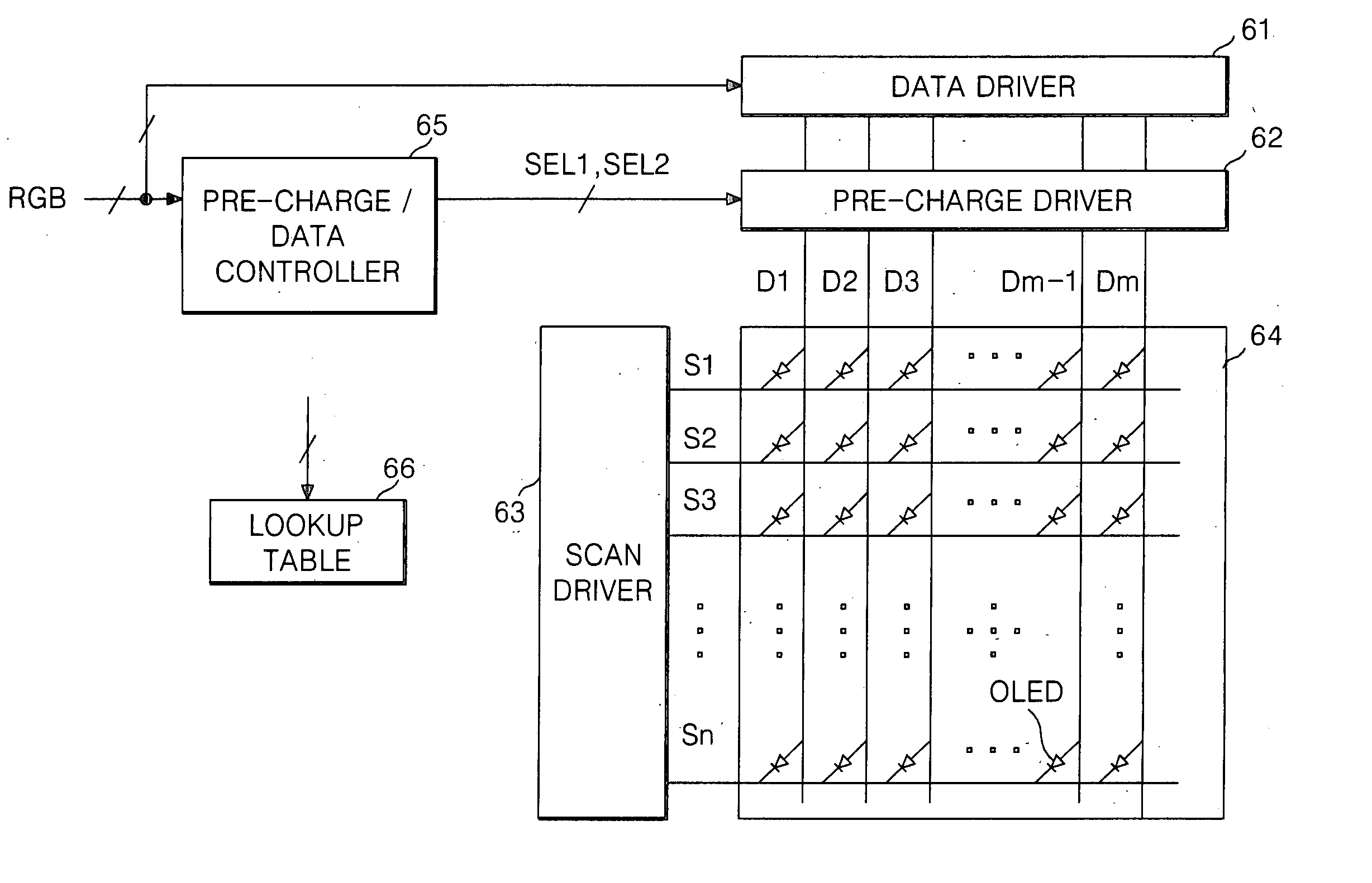
[0057] Referring to FIG. 7, the organic EL display device according to the present invention includes a display panel 64 where m×n numbers of organic EL elements OLED are arranged in a matrix type; a data driver 61 to generate a data current; a pre-charge driver 62 to generate a pre-charge current; a scan driver 63 to generate a scan pulse which is synchronized with the data current; and a pre-charge / data controller 65 to control the pre-charge driver 62 in accordance with a lookup table 66.

[0058] In the display panel 64, m numbers of data lines D1 to Dm and n numbers of scan lines S1 to Sn cross each other and the organic EL elements OLED are arranged between intersections thereof.

[0059] The data driver 61 includes a shift register circuit to sequentially sample data, and a current source of a current mirror circuit or a current sink circuit. The data driver 61 samples a digital video data and supplies a data current corresponding to the gray level value of the digital video data ...

second embodiment

[0079] Referring to FIG. 12, an organic electro luminescence display device according to the present invention includes a display panel 164 in which m×n numbers of organic EL elements OLED are arranged in a matrix type; a data driver 161; a pre-charge driver 162; a scan driver 163; a data comparison part 167; a gray level judgment part 166; and a pre-charge controller 165.

[0080] In the display panel 164, m numbers of data lines D1 to Dm and n numbers of scan lines S1 to Sn cross each other and the organic EL elements OLED are arranged between intersections thereof.

[0081] The data driver 161 includes a shift register circuit to sequentially sample data, and a current mirror circuit or a current sink circuit. The data driver 161 samples a digital video data and supplies a data corresponding to the gray level value of the data to the data lines D1 to Dm through the pre-charge driver 162.

[0082] The pre-charge driver 162, under control of the pre-charge / data controller 65, is charged w...


PUM


Abstract

The present invention relates to an organic electro luminescence display device using a pre-charge, and a driving method thereof. An organic electro luminescence display device according to an embodiment of the present invention includes: a display panel where a plurality of data lines cross a plurality of gate lines, and electro luminescence elements are arranged at intersections thereof; a pre-charge driver to select a current which is different in accordance with a gray level of data and to supply the pre-charge current to the electro luminescence elements through the data line; and a data driver to supply a data to the electro luminescence elements which are charged with the pre-charge current.

Description

[0001] This application claims the benefit of the Korean Patent Application Nos. P2004-39748 and P2004-42115 filed on Jun. 1, 2004, and, on Jun. 9, 2004 which are hereby incorporated by reference. BACKGROUND OF THE INVENTION [0002] 1. Field of the Invention [0003] The present invention relates to an electro luminescence display device, and more particularly to an organic electro luminescence display device using a pre-charge, and a driving method thereof. [0004] 2. Description of the Related Art [0005] Recently, there have been developed various flat panel displays that can reduce their weight and size which are the disadvantages of the cathode ray tube CRT. The flat panel display includes the liquid crystal display LCD, the field emission display FED, the plasma display panel PDP, the electro luminescence EL display device and etc. [0006] The PDP is relatively simple in its structure and fabricating process, thus it is most advantageous in being made into large screen, but there is...

Claims


Application Information

Patent Timeline
IPC IPC(8): G09G3/30G09G3/20G09G3/32
CPCG09G3/3216G09G2330/021G09G2310/0248G09G2300/0408
Inventor KIM, HAK SULEE, JAE DOHA, WON KYU
Owner LG DISPLAY CO LTD
Why Eureka
Try Eureka