Illumination apparatus and image-taking apparatus

a technology which is applied in the field of illumination apparatus and imagetaking apparatus, can solve the problems of reducing the irradiation efficiency of illumination light, increasing the size or cost of the resulting illumination apparatus, and difficult to ensure sufficient illumination in peripheral areas other than the central area, so as to reduce uneven color, efficient condense light, and reduce uneven effects

Inactive Publication Date: 2005-12-01
CANON KK
View PDF12 Cites 11 Cited by
  • Summary
  • Abstract
  • Description
  • Claims
  • Application Information

AI Technical Summary

Benefits of technology

[0018] It is an object of the present invention to provide an illumination apparatus, which can efficiently condense light from a light source such as an LED. It is another object of the present invention to provide an illumination apparatus in which uneven light distribution and uneven color can be reduced.

Problems solved by technology

Specifically, no problem occurs when it is possible to select an LED which can irradiate light to an optimal irradiation area required for an optical device on which the LED is mounted, but the irradiation area of an LED is not always identical to the optimal irradiation area of the optical device.
In this case, the addition of the other optical system increases the size or cost of the resulting illumination apparatus.
Thus, part of luminous flux emerging from the LED escapes from the space to reduce the irradiation efficiency of the illumination light.
In the light-condensing optical system which uses the convex lens to utilize only refracted light, while the central area (the area near the irradiation optical axis) of the light irradiation area can be irradiated relatively brightly, sufficient illuminance is difficult to ensure in peripheral areas other than the central area.
It is thus difficult to provide illumination of uniform brightness over the entire required irradiation area.
In the aforementioned illumination optical system, however, luminous flux near the irradiation optical axis is merely condensed sequentially while the emergence direction thereof is changed by refraction or reflection, and the optical system is not formed to improve the light-condensing efficiency by making use of refraction and reflection.
In such a structure, however, the luminous flux emerging from the LED cannot be necessarily used efficiently as described above, and the illuminance distribution in the illumination area is not always uniform.
When a light source having LED elements of a plurality of colors packaged together for a single condenser lens is used, these LED elements are arranged at different positions and it is difficult to match the irradiation areas of the respective LED elements.
This results in unevenly distributed light and uneven color.
When the diffusing component is contained, however, it is generally known that the irradiation efficiency is extremely reduced, and an optical system cannot be formed with high irradiation efficiency.

Method used


Image

  • Illumination apparatus and image-taking apparatus
  • Illumination apparatus and image-taking apparatus
  • Illumination apparatus and image-taking apparatus

Examples


embodiment 1

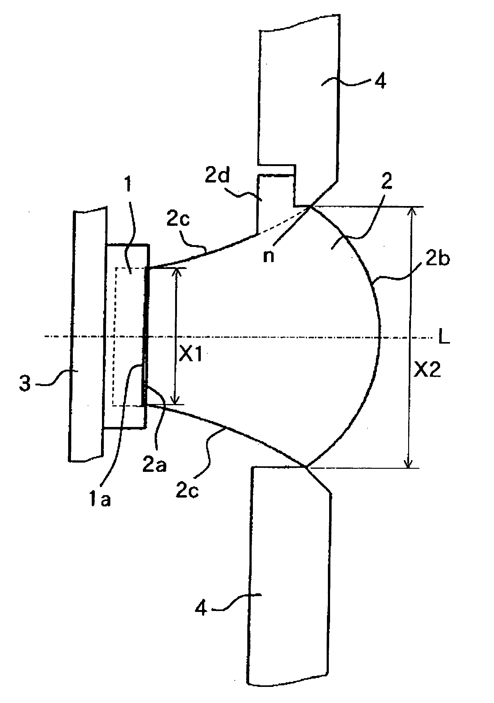
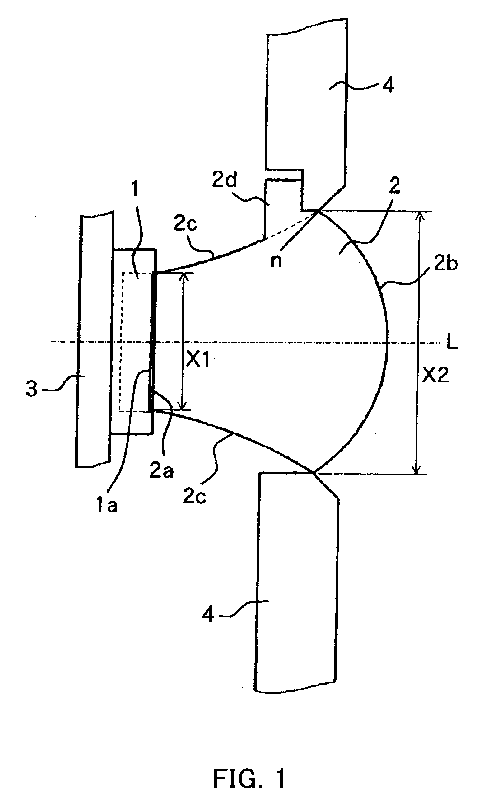
[0043] FIGS. 1 to 7 are diagrams for explaining an illumination unit (illumination apparatus) of Embodiment 1 of the present invention and a video camera (image-taking apparatus) having the illumination unit. The illumination unit of Embodiment 1 can efficiently condense luminous flux emerging from a minute surface light source such as an LED as described below.

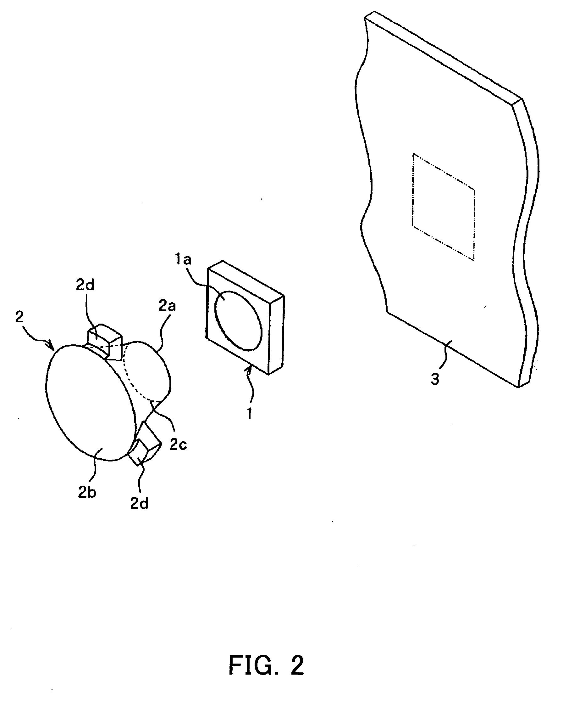
[0044]FIG. 1 is a longitudinal section view showing the structure of the illumination unit of Embodiment 1. FIG. 2 is a perspective view showing the outer appearance of main optical systems of the aforementioned illumination unit. FIG. 3 is a front view showing an optical member disposed inside the aforementioned illumination unit.

[0045]FIGS. 4A to 4I are diagrams for explaining the light distribution characteristic of the aforementioned illumination unit and show the traces of luminous flux incident on the light source from the side of light irradiation. FIGS. 4A to 4I are the diagrams obtained when the angle of the aforem...

embodiment 2

[0101] FIGS. 8 to 14 are diagrams for explaining an illumination unit which is Embodiment 2 of the present invention. The illumination unit of Embodiment 2 employs an LED unit which has a plurality of LED elements emitting different colors arranged in a single package.

[0102]FIG. 8 is a longitudinal section view showing the structure of the illumination unit of Embodiment 2. FIG. 9 is a perspective view showing the outer appearance of the structure of the illumination unit of Embodiment 2. FIG. 10 is a front view showing the LED unit for use in Embodiment 2.

[0103]FIG. 11 shows the distribution of the irradiation ranges of the respective LED elements relative to a required irradiation range when a condenser lens (the condenser lens 22 shown in FIGS. 5A to 5G) is disposed for condensing in front of the LED unit shown in FIG. 10 (on the side of light emergence).

[0104] FIGS. 12 to 14 are diagrams for explaining how luminous flux emerging from one LED in the LED unit is condensed by ea...

embodiment 3

[0143] FIGS. 15 to 18 are diagrams for explaining an illumination unit which is Embodiment 3 of the present invention. The illumination unit of Embodiment 3 is optimal especially when a white-color LED obtained by combining a blue-color LED with a phosphor is used as a light source.

[0144]FIG. 15 is a longitudinal section view showing the structure of the illumination unit of Embodiment 3. FIG. 16 is provided by adding, to the longitudinal section view of FIG. 15, the light ray traces of a component at a smaller angle with respect to an irradiation optical axis of luminous flux emerging from the center of the LED. FIG. 17 is provided by adding, to the longitudinal section view, the light ray traces of a component at a larger angle with respect to the irradiation optical axis of the luminous flux emerging from the center of the LED.

[0145]FIG. 18 is a section view for explaining the structure of the white-color LED. FIG. 19 is a longitudinal section view showing the structure of an i...


PUM


Abstract

An illumination apparatus is disclosed, which can efficiently condense light from a light source such as an LED. The illumination apparatus has a light source and an optical member disposed on the side of light irradiation of the light source. The optical member has an incident surface, an emergent surface having a positive optical power, and a reflecting surface reflecting part of light from the incident surface and leading it to the emergent surface. The reflecting surface is formed further away from an irradiation optical axis than a normal to the emergent surface at a position of the emergent surface closest to the reflecting surface.

Description

BACKGROUND OF THE INVENTION [0001] The present invention relates to an illumination apparatus, which has an optical member for efficiently condensing luminous flux emerging from a light source such as a light-emitting diode to a required irradiation area, and an image-taking apparatus, which has the illumination apparatus. [0002] Conventionally, a number of illumination apparatuses employing a light-emitting diode (hereinafter abbreviated to “LED”) as a light source have been put into practical use in which the LED is provided with a light-condensing function. The LED of this type is formed to have a light-emitting diode chip fixed inside a metal cup serving as a reflecting mirror and a dome-shaped transparent resin having a light-condensing function formed on the front surface (the surface on the emergence side) of the metal cup. [0003] The LED of the aforementioned structure can provide different degrees of light condensing by changing the diameter or curvature of the portion of t...

Claims


Application Information

Patent Timeline
Patent Type & Authority Applications(United States)
IPC IPC(8): F21V5/04G03B15/02F21V13/02F21Y101/02G03B15/03G03B15/05H01L33/58H04N5/222H04N5/225
CPCG03B15/05H04N5/2256G03B2215/0503H04N23/56
Inventor TENMYO, YOSHIHARU
Owner CANON KK
Why Eureka
Try Eureka