Hard biased materials for recording head applications

Inactive Publication Date: 2005-12-01
HEADWAY TECH INC
View PDF23 Cites 15 Cited by
  • Summary
  • Abstract
  • Description
  • Claims
  • Application Information

AI Technical Summary

Benefits of technology

[0014] A further objective of the present invention is to provide a hard bias layer that does not require an underlying seed layer so that a direct contact is made between the hard bias layer and an adjacent fre

Problems solved by technology

A problem occurs when an edge demagnification effect leads to hard bias magnetization canting in which the in-plane magnetization vector in the hard bias layer is partially shunted away from the free layer.
Thus, the hard bias layers 8 may not provi

Method used


Image

  • Hard biased materials for recording head applications
  • Hard biased materials for recording head applications
  • Hard biased materials for recording head applications

Examples


first embodiment

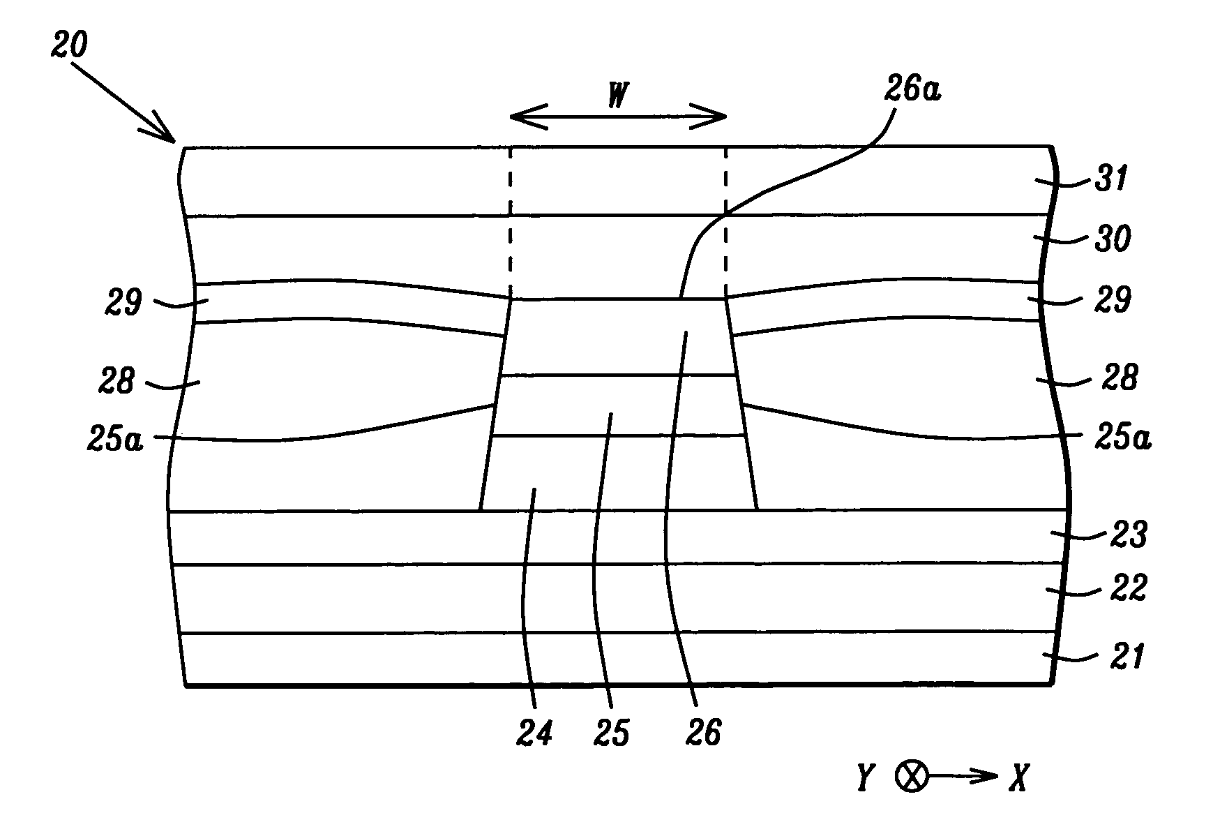
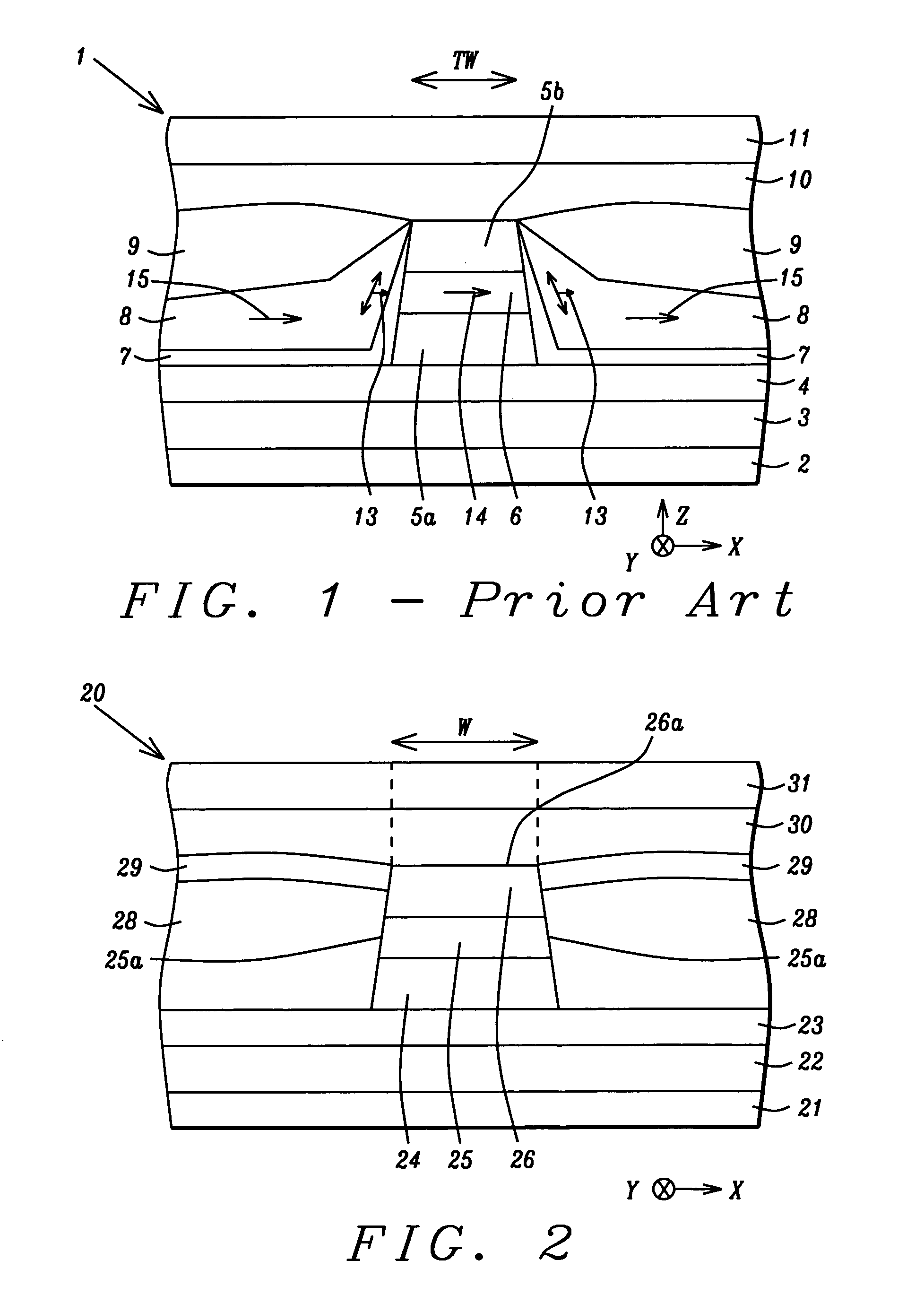
[0025] A first embodiment is depicted in FIG. 2 in which a magnetic read head is comprised of a GMR element and a novel hard bias layer which forms an abutting junction with a free layer in the GMR element. The GMR element may be comprised of either a top spin valve or a bottom spin valve.

[0026] Referring to FIG. 2, a cross-sectional view from an ABS plane is shown of a magnetic read head 20 which has a substrate 21 that may be a ceramic layer, for example. A first shield 22 is formed on the substrate 21 and a first gap layer 23 is formed on the first shield. There is a GMR element comprised of a bottom portion 24, a free layer 25, and a top portion 26 sequentially formed on the first gap layer 23. The GMR element typically has sloped sidewalls wherein the top portion 26 has a smaller width than the bottom portion 24. The GMR element has a total thickness of about 100 to 500 Angstroms.

[0027] In one embodiment that represents a bottom spin valve, the bottom portion 24 is comprised o...

second embodiment

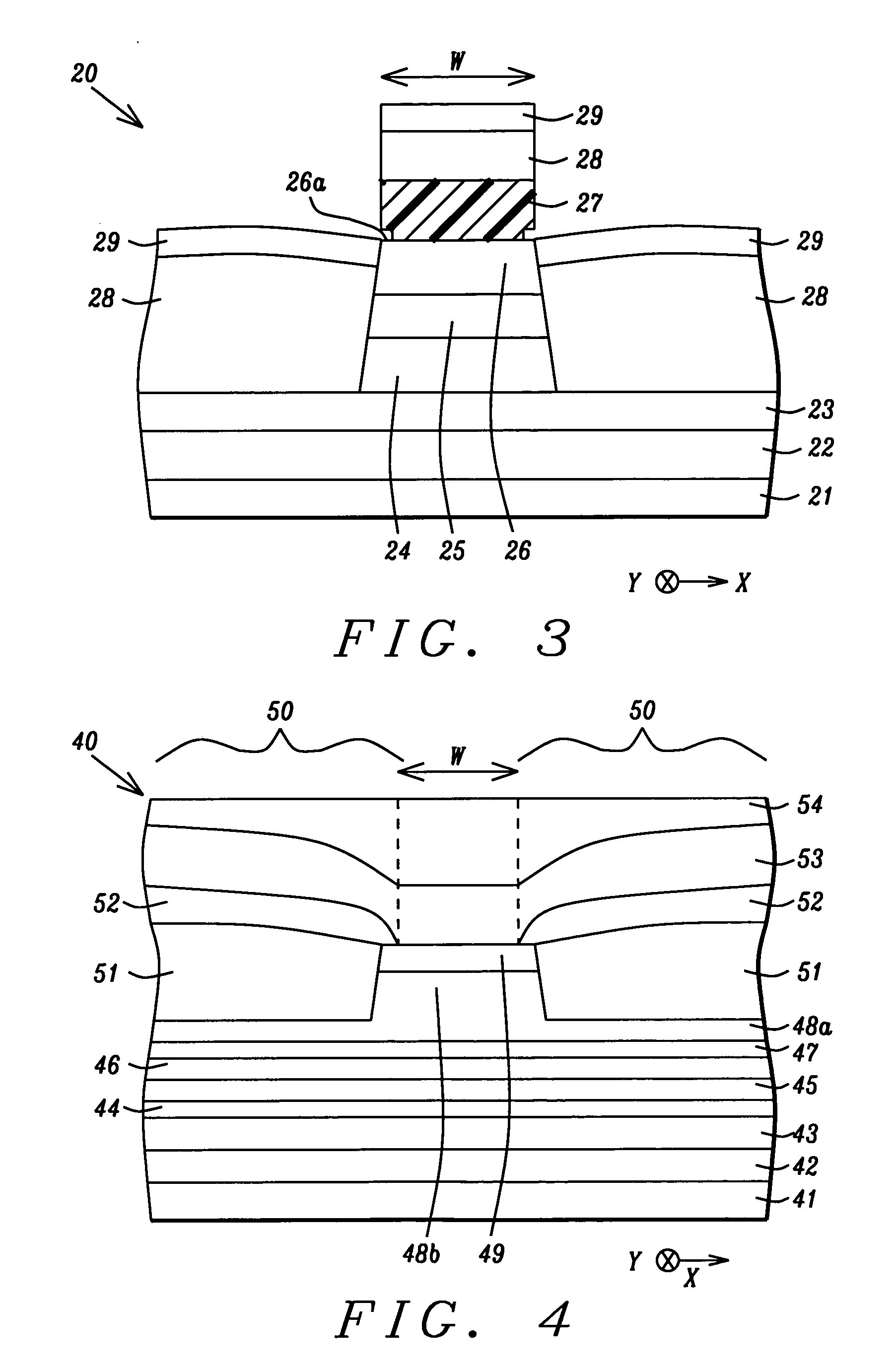
[0042] the present invention is a magnetic read head shown in FIG. 4 in which a cap layer and an upper portion of a free layer have a first width that is smaller than a second width of a lower portion of the free layer and the remainder of the underlying layers in the bottom spin valve structure. A novel hard bias layer according to the present invention forms an abutting junction along the sidewalls of the upper portion of the free layer and along the top surface of the bottom portion of the free layer.

[0043] Referring to FIG. 4, a cross-sectional view from an ABS plane depicts a magnetic read head 40 that has a substrate 41 on which a first shield 42 and a first gap layer 43 are consecutively formed. A GMR element which is a stack of layers that has a bottom spin valve configuration is formed on the first gap layer 43 and has a bottom seed layer 44 which may be NiCr, for example. There is an AFM pinning layer 45 on the seed layer 44 and a pinned layer 46 which may have a SyAP conf...


PUM


Abstract

A hard bias layer that forms an abutting junction with a free layer in a GMR element and is comprised of FePtCu or FePtCuX where X is B, C, O, Si, or N is disclosed. The FePtCu layer has a composition of about 45 atomic % Fe, 45 atomic % Pt, and 10 atomic % Cu and does not require a seed layer to achieve an ordered structure. The FePtCu layer is annealed at a temperature of about 280° C. and has an Hc value more than double that of a conventional CoCrPt hard bias layer with a similar thickness. Since the FePtCu hard bias layer adjoins a free layer, it has a higher sensor edge pinning efficiency than a configuration with a CoCrPt layer on a seed layer. The novel hard bias layer is compatible with either a top or bottom spin valve structure in a GMR sensor.

Description

FIELD OF THE INVENTION [0001] The invention relates to the fabrication of a giant magnetoresistive (GMR) sensor in a magnetic read head and in particular to an improved hard bias material having a high coercivity and sensor edge pinning efficiency that does not require a seed layer. BACKGROUND OF THE INVENTION [0002] A magnetic disk drive includes circular data tracks on a rotating magnetic disk and read and write heads that may form a merged head attached to a slider on a positioning arm. During a read or write operation, the merged head is suspended over the magnetic disk on an air bearing surface (ABS). The sensor in a read head is a critical component since it is used to detect magnetic field signals by a resistance change. One form of magnetoresistance is a spin valve magnetoresistance (SVMR) or giant magnetoresistance (GMR) which is based on a configuration in which two ferromagnetic layers are separated by a non-magnetic conductive layer in the sensor stack. One of the ferrom...

Claims


Application Information

Patent Timeline
IPC IPC(8): G11B5/127G11B5/33G11B5/39
CPCG11B5/39Y10T428/11Y10T428/115
Inventor LI, YUN-FEIZHANG, KUNLIANGTORNG, CHYU-JIUH
Owner HEADWAY TECH INC
Why Eureka
Try Eureka