General code design for the relay channel and factor graph decoding

a factor graph and relay channel technology, applied in the field of general code design of relay channels and factor graph decoding, can solve the problems of providing a practical level of decoding complexity, direct transmission between the base station and the mobile terminal that is close to the cell boundary can be very expensive, and the design of the relay channel, so as to and improve the decoding accuracy

Inactive Publication Date: 2005-12-01
NOKIA CORP
View PDF5 Cites 66 Cited by
  • Summary
  • Abstract
  • Description
  • Claims
  • Application Information

AI Technical Summary

Benefits of technology

[0012] In accordance with one embodiment of the invention, a relay channel comprises a source node that is adapted to transmit a plurality of codewords, a relay node that is coupled to receive the plurality of codewords and is adapted to transmit an estimate for each codeword received. The relay channel further comprises a destination node that is coupled to simultaneously receive a superposition of the plurality of codewords and estimates of the plurality of codewords and is adapted to decode each transmitted codeword using partial factor graph decoding. The codeword estimate improves the accuracy of the decoded codeword.
[0013] In accordance with another embodiment of the invention, a method of forward decoding information blocks of a relay channel comprises receiving a first information block at a relay node and a destination node, estimating the first information block at the relay node, receiving a superposition of a second information block and the first information block estimate at the destination node, and jointly decoding the first and second information blocks at the destination node. The first information block estimate improves a decoding accuracy of the second information block.
[0014] In accordance with another embodiment of the invention, a method of reverse decoding information blocks of a relay channel comprises receiving a predetermined number of information blocks at a relay node and a destination node, estimating the last information block received at the relay node, receiving a superposition of a next to last information block and the last information block estimate at the destination node, and jointly decoding the last and the next to last information blocks at the destination node. The last information block estimate improves a decoding accuracy of the next to last information block.

Problems solved by technology

A central challenge with coding theory has always been to devise a coding scheme that comes close to achieving the channel capacity, while providing a practical level of decoding complexity.
Another motivation for using a relay channel comes from the realization that in the case of a cellular network, for example, direct transmission between the base station and mobile terminals that are close to the cell boundary can be very expensive in terms of the transmission power required to insure reliable communications.
Accordingly, the primary difficulty of code design for the relay channel, which makes it completely different from ordinary single link coding, is due to the importance of the design of an effective causal relaying function.
While this technique improves upon multi-hopping, it nevertheless suffers from a considerable rate loss, since no new information is transmitted during the time that relaying is performed.
Furthermore, while recent information theoretical results have shown a considerable improvement in the performance of communication systems through the use of relaying and cooperation, there has been almost no development in the area of real code design for the relay channel.

Method used


Image

  • General code design for the relay channel and factor graph decoding
  • General code design for the relay channel and factor graph decoding
  • General code design for the relay channel and factor graph decoding

Examples


first embodiment

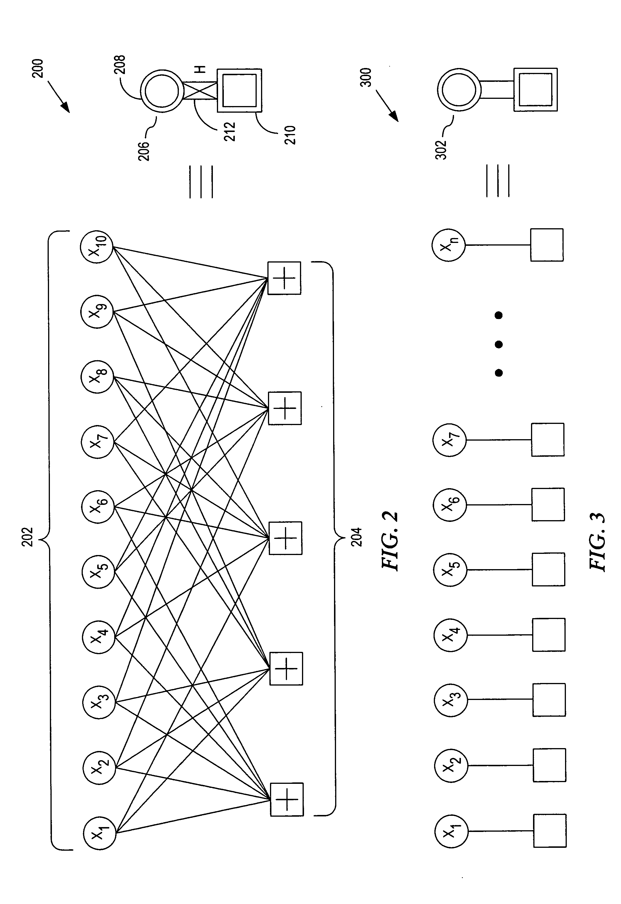
[0058] In a first embodiment, joint decoding of all B blocks is performed by solving factor graph 400 using a MAP algorithm for an optimal decoding strategy. If constituent codes, e.g., H2 and H3, are chosen to be LDPC codes, however, then it is possible to use the practically implementable method of belief propagation as the optimal decoding strategy. The same method of belief propagation may also be extended for use where the constituent codes are either convolutional or turbo codes. The factor graph representation of these codes and their corresponding decoding schemes is known and will not be further discussed herein.

second embodiment

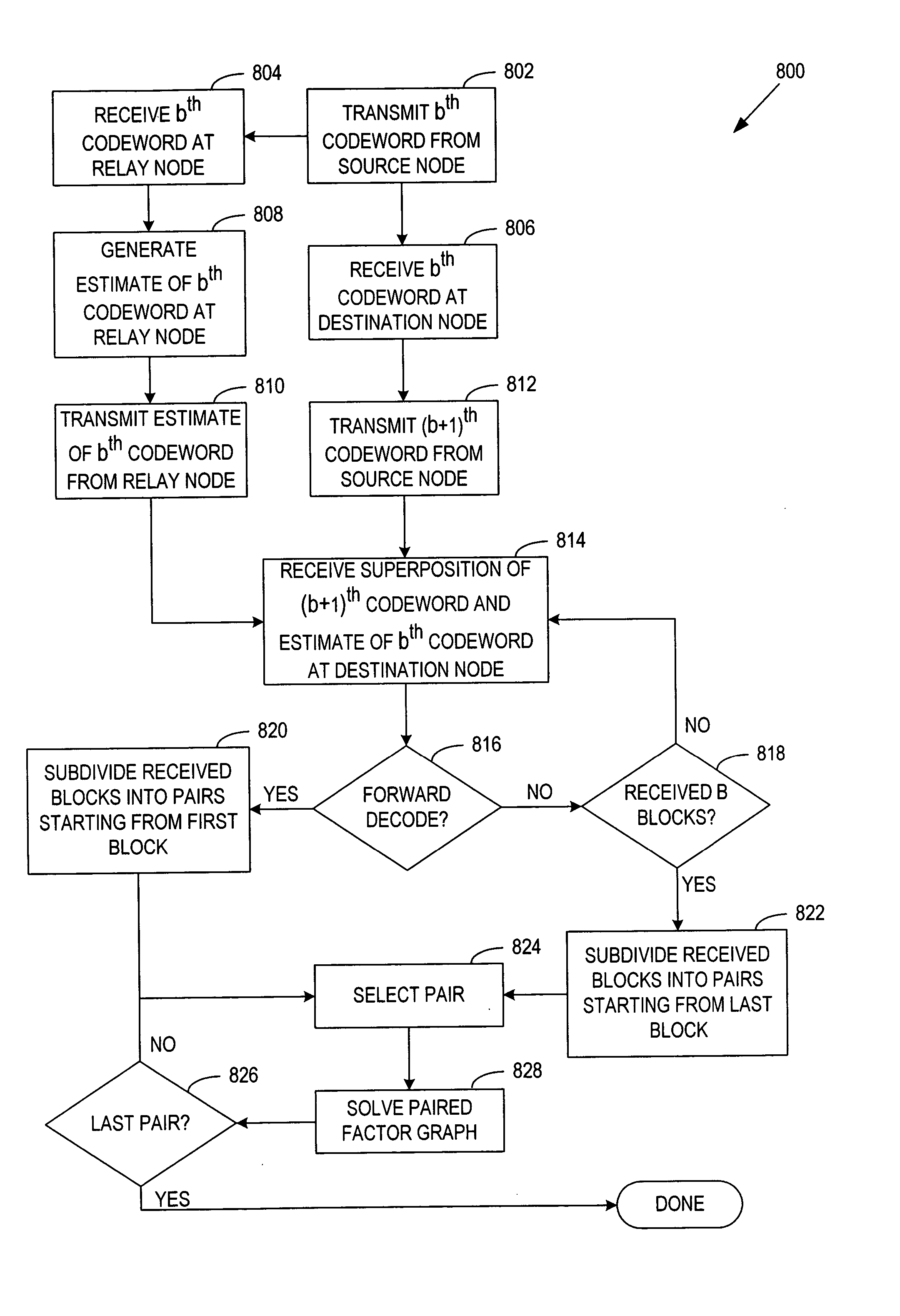
[0059] In a second embodiment according to the present invention, the original factor graph of the code as illustrated in FIG. 4 is broken down into a sequence of smaller factor graphs 602-606, called partial factor graphs, as exemplified in FIG. 6. Two successive decoding schemes, the forward decoding scheme and the reverse decoding scheme, may then be applied to the partial factor graphs 602-606, each of which exhibit very good performance with orders of magnitude lower decoding complexity as compared to the joint decoding of all B blocks as illustrated in FIG. 4. It should be noted that if the constituent codes are some other form of block codes, such as turbo codes or convolutional codes, the same forward or backward decoding schemes can still be successfully exploited. The challenge remains, however, to find the optimal joint design of the block codes for the coding structures of FIG. 4 and FIG. 6.

[0060] In the forward decoding scheme, as depicted by directional arrows 608 of F...


PUM


Abstract

A system and method of relay code design and factor graph decoding using a forward and a backward decoding scheme. The backward decoding scheme exploits the idea of the analytical decode-and-forward coding protocol and hence has good performance when the relay node is located relatively close to the source node. The forward decoding scheme exploits the idea of the analytical estimate-and-forward protocol and hence has good performance when the relay node is located relatively far from the source node. The optimal decoding factor graph is first broken into partial factor graphs and then solved iteratively using either the forward or backward decoding schemes.

Description

[0001] This application claims the benefit of U.S. Provisional Application No. 60 / 575,877 filed 1 Jun. 2004, the content of which is incorporated herein by reference in its entirety.FIELD OF THE INVENTION [0002] This invention relates in general to communication systems, and more particularly to a code design for a relay channel and its associated factor graph decoding. BACKGROUND OF THE INVENTION [0003] The past decade has been exciting in terms of the advances introduced in channel coding technology. Coding theory advancement is motivated by the lure of reliable communications over noisy channels at increasingly higher code rates. A central challenge with coding theory has always been to devise a coding scheme that comes close to achieving the channel capacity, while providing a practical level of decoding complexity. [0004] Advancements in coding theory have led to the development of code families such as turbo codes, Low-Density Parity Check (LDPC) codes, and others, that with s...

Claims


Application Information

Patent Timeline
Patent Type & Authority Applications(United States)
IPC IPC(8): H03M13/29H04J3/16H04L1/00H04L1/06
CPCH04L1/0041H04L1/0045H04L2001/0097H04L1/0057H04L1/06H04L1/005H03M13/1102H03M13/1111H03M13/1191H03M13/23H03M13/2957H03M13/3761
Inventor KHOJASTEPOUR, MOHAMMAD ALIAHMED, NASIRAAZHANG, BEHNAAM
Owner NOKIA CORP
Why Eureka
Try Eureka