Method for processing receiver signal and optical sensor

a receiver signal and optical sensor technology, applied in the field of processing receiver signals and optical sensors, can solve the problems of undesirable reduction of the detection sensitivity of the light grid, the disadvantage of analog circuits of this type, and the inability to detect external interference, so as to achieve the effect of increasing the detection sensitivity of the optical sensor

Inactive Publication Date: 2005-12-01
LEUZE LUMIFLEX GMBH & CO KG
View PDF5 Cites 6 Cited by
  • Summary
  • Abstract
  • Description
  • Claims
  • Application Information

AI Technical Summary

Benefits of technology

[0009] It is therefore an object of the present invention to provide a method for processing received signals so that the detection sensitivity of an optical sensor is increased.
[0012] As a result of filtering the receiver output signal by the filtering matrix, the interfering signal portion in the receiver output signal can be suppressed while the useful signal portion in the receiver output signal can simultaneously be emphasized, thus considerably increasing the detection sensitivity of the optical sensor for which the signal evaluation according to the invention is realized.
[0018] To eliminate the interfering signal components in the individual receiver output signals, generated in this way, the filtering matrix is composed of an averaging component and a difference-forming component. It is particularly advantageous if the filtering matrix consists of a sequence of matrix values (1, 1, −1, −1), meaning that for generating a value for the filtered receiver output signal, the first two scanning values of the receiver output signal are added during one scanning step and that the following two scanning values are subtracted from this sum.
[0021] The first three scanning values of a scanning step can be taken over from the preceding scanning step since the sequence of values obtained in one scanning step is offset relative to the sequence of scanning values in the preceding scanning step by precisely the time interval Δt, which can also be used for generating the scanning values within one scanning step. This leads to a considerable simplification of the signal evaluation and thus to a significant reduction in the required, computation time.
[0023] For one particularly preferred embodiment of the invention, an adaptive threshold value that is derived from the course of the unfiltered receiver output signal is used to evaluate the filtered receiver output signal. The threshold value advantageously is determined through averaging over the course of the receiver output signal. In particular for a light grid, several receiver output signals are generated cyclically and successively, wherein a predetermined number of receiver output signals is advantageously stored, so that the threshold value can be computed through averaging over several receiver output signals. By computing the threshold value in this way, the adaptive threshold value is already adapted to the course of the receiver output signal. The averaging also eliminates interfering signal influences, so that these do not influence the determination of the threshold value.

Problems solved by technology

Analog circuits of this type have the disadvantage of being sensitive to external interfering influences, for example EMC (electromagnetic compatibility) interfering influences and thermal drifts of the individual components.
Such interfering influences lead to distorted and falsified received signals and, in the final analysis, also to incorrect object detections which consequently lead to an undesirable reduction in the detection sensitivity of the light grid.

Method used


Image

  • Method for processing receiver signal and optical sensor
  • Method for processing receiver signal and optical sensor
  • Method for processing receiver signal and optical sensor

Examples


Embodiment Construction

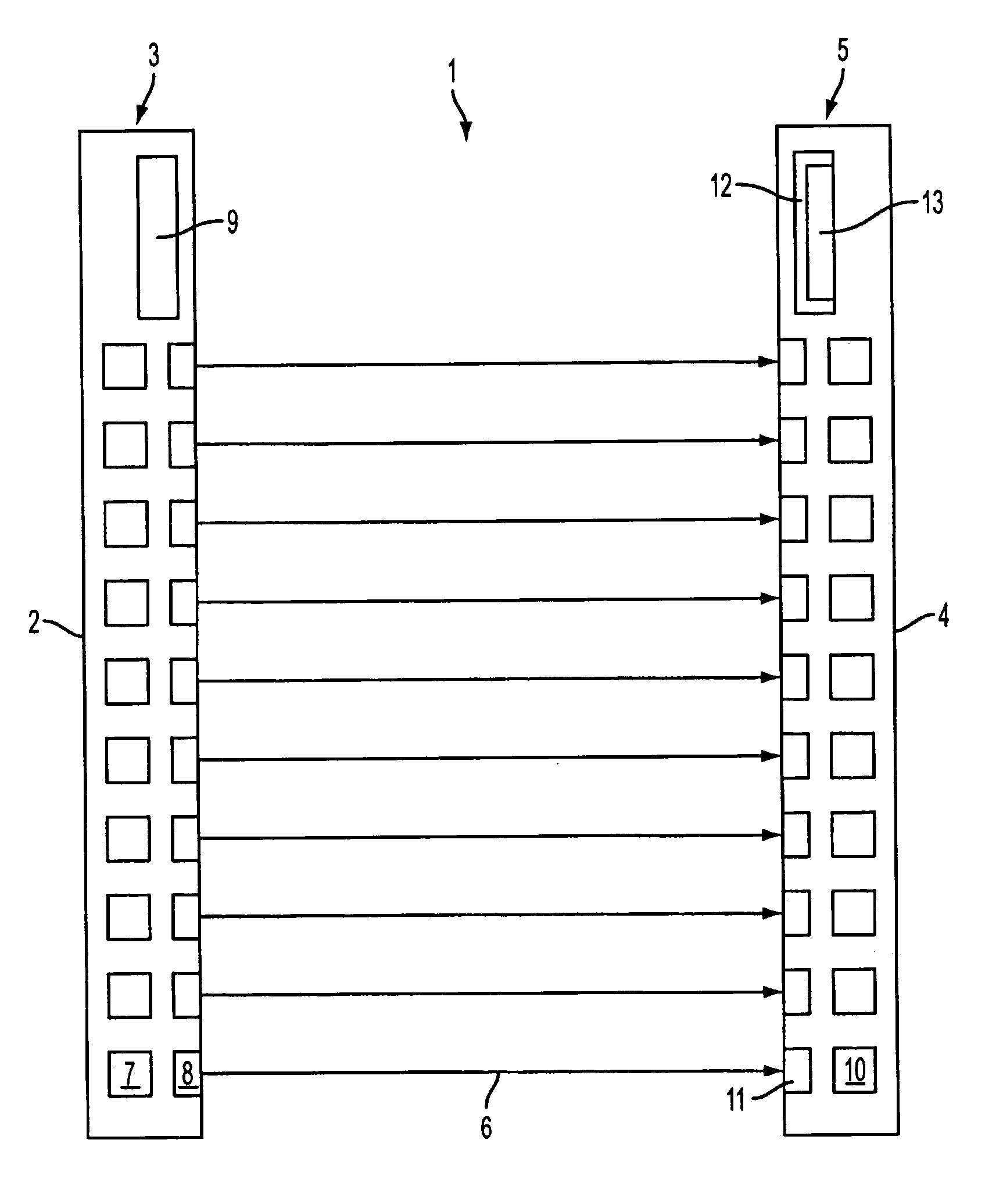
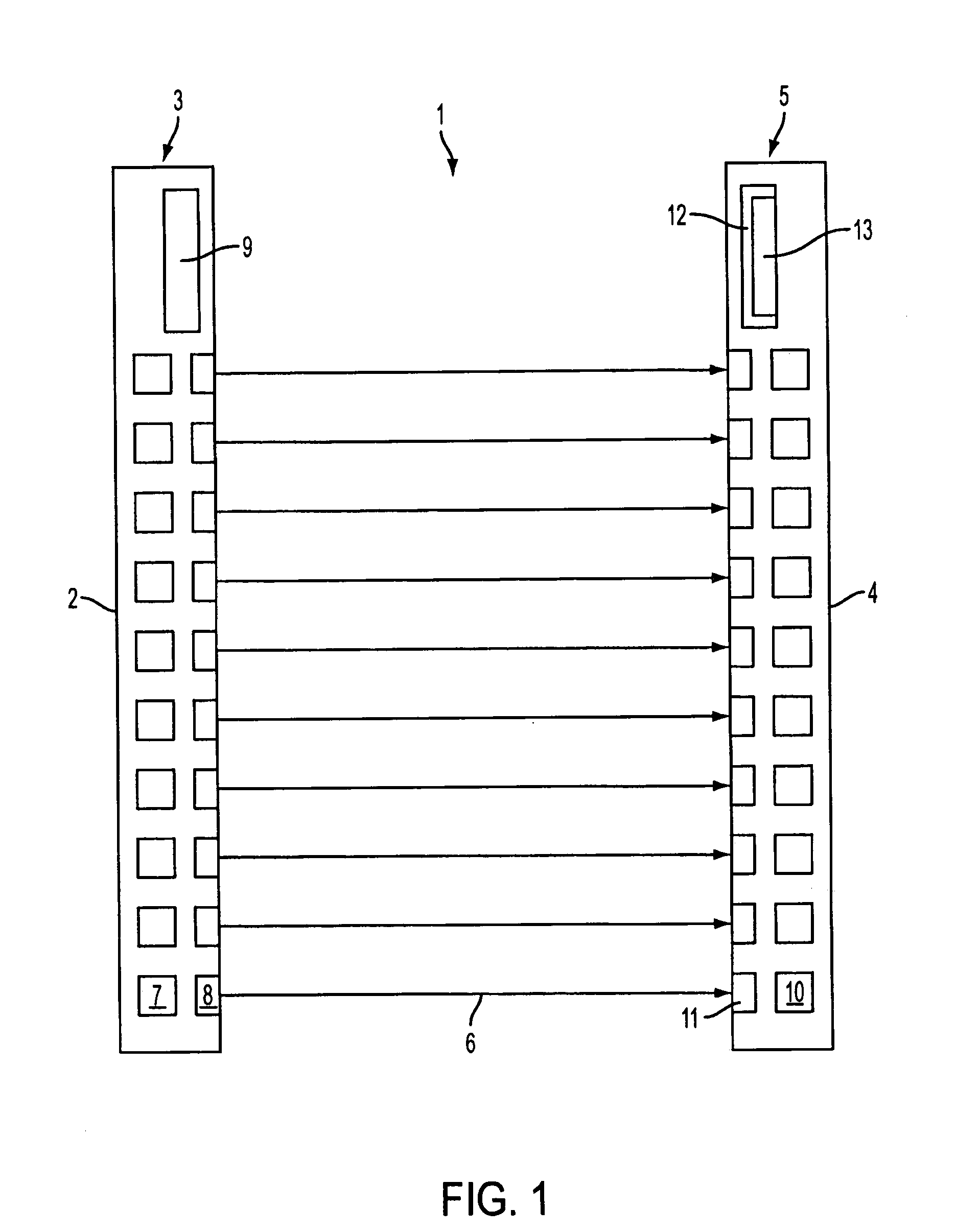
[0031]FIG. 1 shows a design of an optical sensor embodied as light grid 1 for monitoring an area to be monitored. The light grid 1 comprises a transmitting unit 3, integrated into a first housing 2, and a receiving unit 5 that is integrated into a second housing 4. The transmitting unit 3 and the receiving unit 5 are positioned on opposite edges of the area to be monitored.

[0032] The transmitting unit 3 comprises an arrangement of transmitters 7 for emitting light rays 6. The transmitters 7 preferably are embodied as identical light-emitting diodes, disposed at a distance next to each other, wherein the transmitters 7 are preferably arranged equidistant along a straight line. Installed downstream of each transmitter 7 is a transmitting optic 8 which forms a beam with the transmitting light rays 6. The respective transmitting optic 8 is installed behind an exit window, not shown separately herein, in the front wall area of the housing 2. The transmitters 7 for this embodiment emit t...


PUM


Abstract

The invention relates to a method for processing a receiver output signal, as well as to an optical sensor. The first method step relates to storing the course of a receiver output signal. In a second method step, the receiver output signal is scanned in a predetermined time interval Δt. The subsequent scanning step relates to correlating the values obtained during the scanning with a filtering matrix, consisting of a sequence of matrix values, for generating a filtered receiver output signal that consists of a discrete sequence of receiver output signal values. In a final method step, the filtered receiver output signal is evaluated with at least one threshold value for generating an object detection signal.

Description

CROSS-REFERENCE TO RELATED APPLICATION [0001] This application is a continuation of application Ser. No. 10 / 996,055, filed Nov. 24, 2004 and claiming the priority of German Patent Application No. 103 55 008.9 filed on Nov. 25, 2003, which priority is also claimed in the present application. The disclosures of the foregoing applications and each U.S. and foreign patent and patent application mentioned herein are incorporated by reference into this application.BACKGROUND OF THE INVENTION [0002] The invention relates to a method for processing a received signal, as well as to an optical sensor. [0003] A known optical sensor in the form of a light grid is provided with a predetermined number of transmitter-receiver pairs which define beam axes or paths. The transmitter-receiver pairs are activated cyclically and successively by an evaluation unit. Each transmitter emits transmitting light rays which are guided onto the associated receiver if the beam path is clear. If at least one beam ...

Claims


Application Information

Patent Timeline
Patent Type & Authority Applications(United States)
IPC IPC(8): G01V8/20H03K17/94
CPCG01V8/20H03K2217/94114H03K17/943
Inventor LOHMANN, LUTZ
Owner LEUZE LUMIFLEX GMBH & CO KG
Why Eureka
Try Eureka