Motor-mounted internal gear pump and electronic device

a technology of internal gear pump and motor, which is applied in the direction of piston pump, positive displacement liquid engine, instrument, etc., can solve the problems of increasing cost and reliability, increasing the size of the entire pump, and deteriorating reliability, and achieves small size and less cost. , the effect of high reliability

Inactive Publication Date: 2005-12-01
HITACHI LTD
View PDF17 Cites 21 Cited by
  • Summary
  • Abstract
  • Description
  • Claims
  • Application Information

AI Technical Summary

Benefits of technology

[0022] The present invention can provide a motor-mounted internal gear pump that is small-sized and less expensive and has...

Problems solved by technology

The pump disclosed in the Patent Reference 1 has a problem that the entire size is increased, so that the pump is made large-sized, since the internal gear pump mechanism and the motor for driving the same are arranged in parallel in the shaft direction.
Providing the shaft sealing device brings problems of increasing...

Method used


Image

  • Motor-mounted internal gear pump and electronic device
  • Motor-mounted internal gear pump and electronic device
  • Motor-mounted internal gear pump and electronic device

Examples


first embodiment

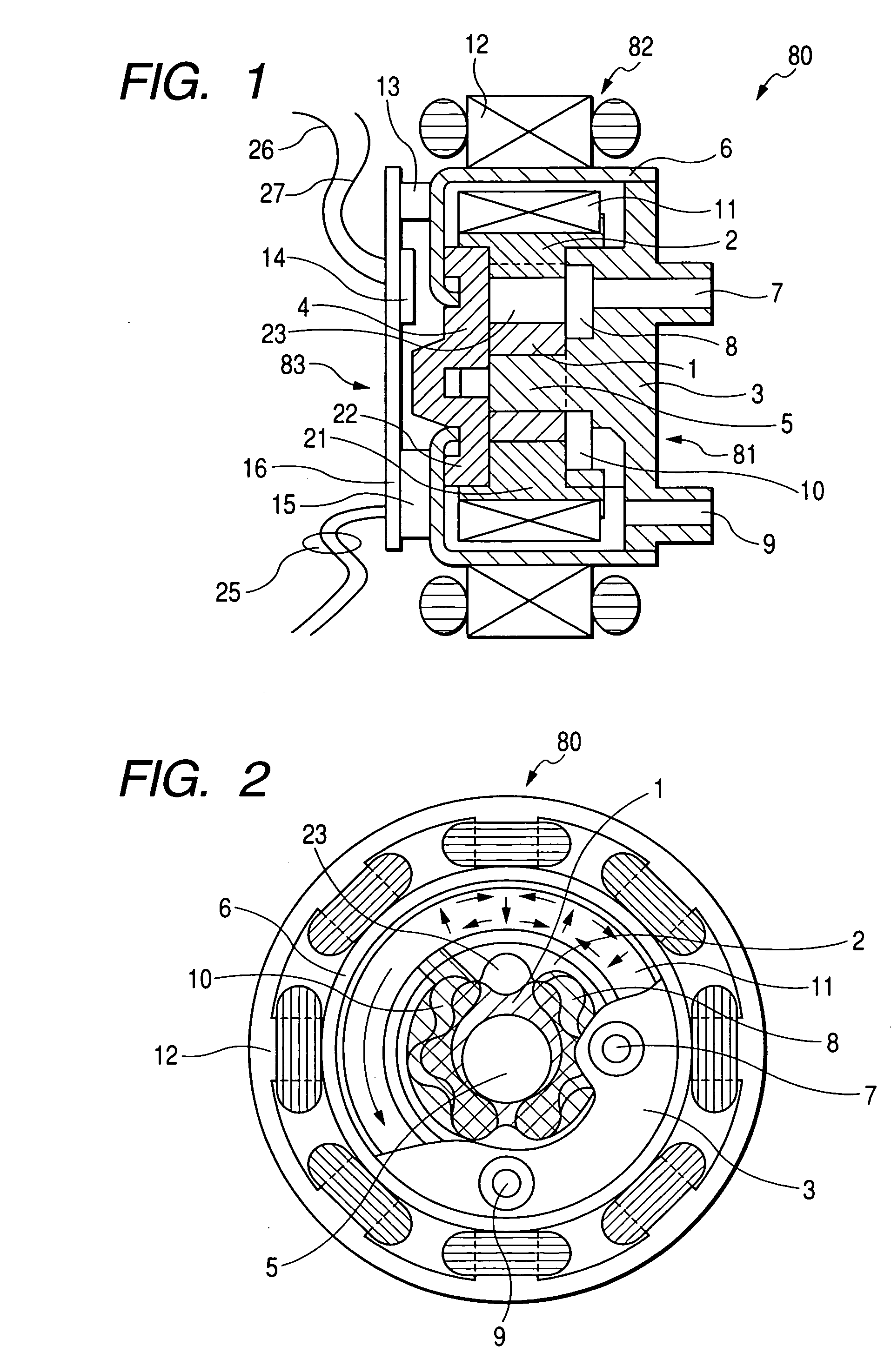
[0031] A motor-mounted internal gear pump and electronic device according to the invention will be explained with reference to FIGS. 1 to 4.

[0032] Firstly, the entire structure of the motor-mounted internal gear pump of this embodiment will be explained by using FIGS. 1 and 2. FIG. 1 is a longitudinal sectional view of the motor-mounted internal gear pump according to the first embodiment of the present invention, while FIG. 2 is a cross-sectional view of the motor-mounted internal gear pump of FIG. 1.

[0033] A pump 80 is a motor-mounted internal gear pump provided with a pump section 81, motor section 82 and control section 83. The pump 80 is formed into a thin-sized shape wherein the size in the diameter direction is greater than the size in the widthwise direction.

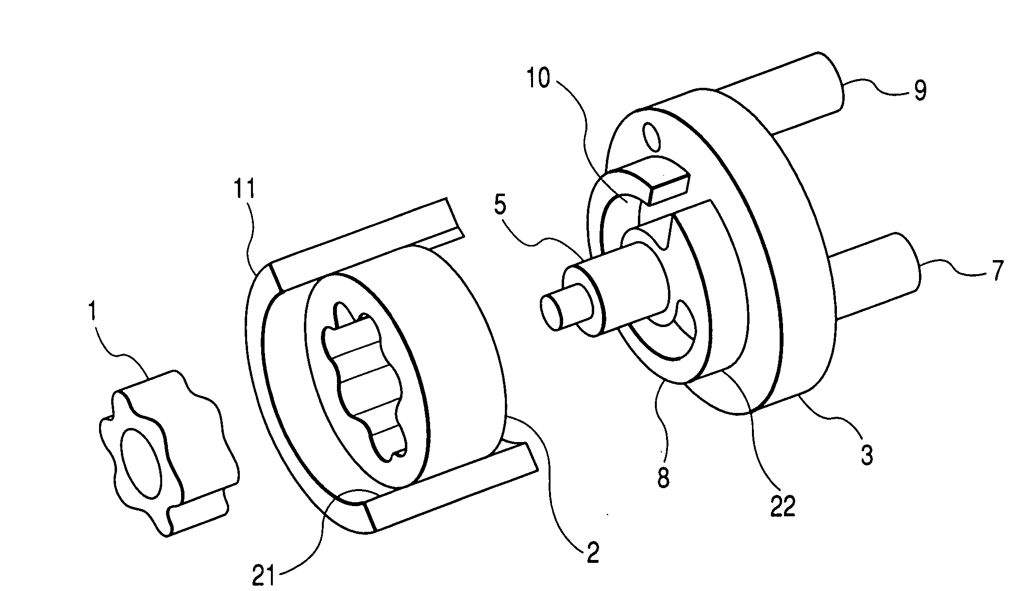
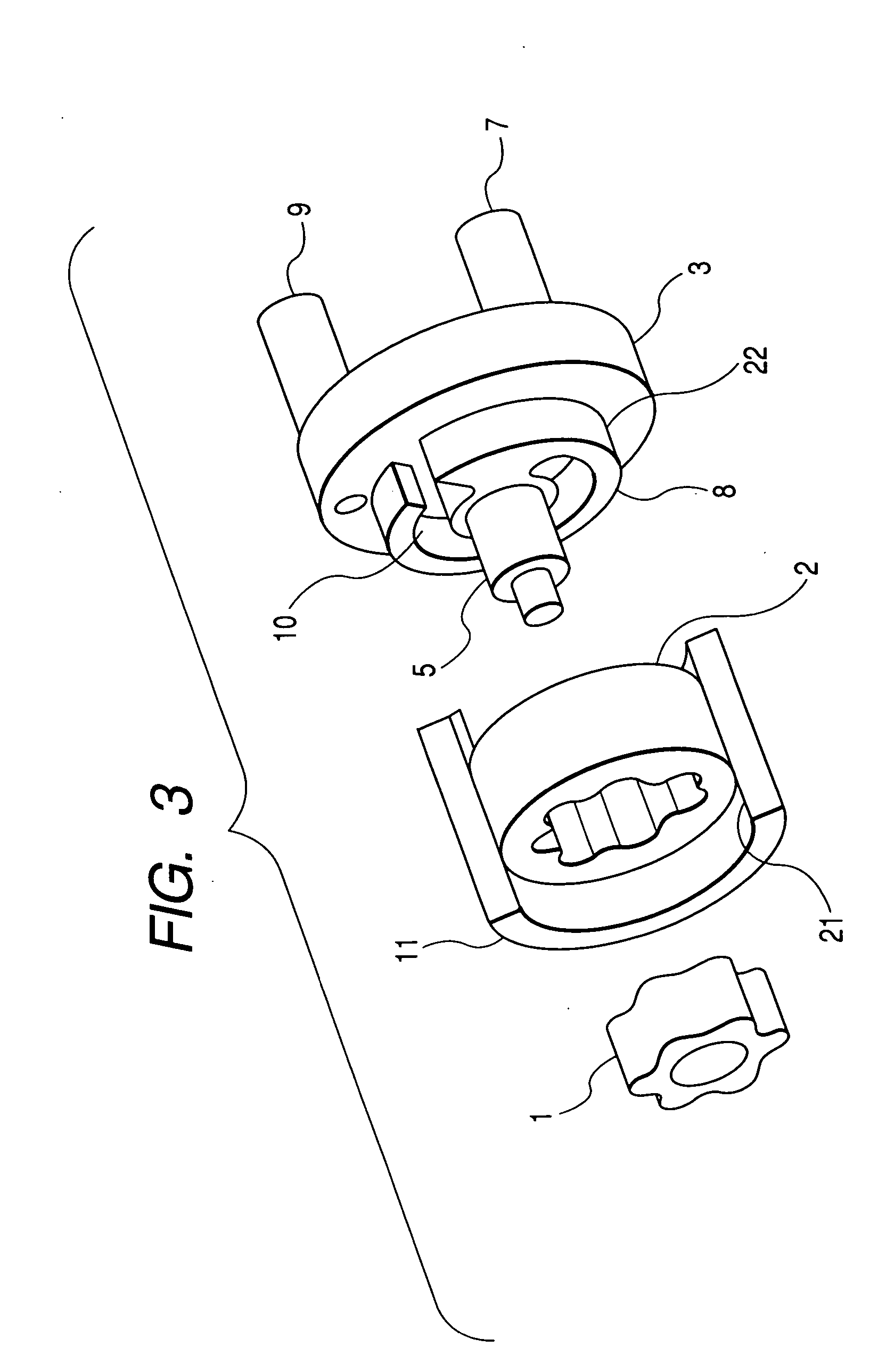
[0034] The pump section 81 is provided with an internal rotor 1, external rotor 2, front plate 3, back plate 4, internal shaft 5 and can 6.

[0035] The internal rotor 1 has a shape similar to a spur gear, wherein teeth ...

second embodiment

[0072] In this second embodiment, the permanent magnet 11 and the stator 12 are arranged so as to be close to one side in the shaft direction with respect to the internal and external rotors 1 and 2. The bracket section 21 is provided so as to project at only one side of the outer peripheral section of the external rotor 2. The permanent magnet 11 is arranged at the outside of the bracket section 21, and the stator 12 is arranged at the outside of the permanent magnet 11. The external rotor 2 is supported only by the shoulder section 22 of the front plate 3 via the bracket section 21. The internal rotor 1 is supported by the shaft 5 embedded into (i.e., integrally molded with) the front plate 3.

[0073] The can 6 is composed of the flange section 6a, cylindrical section 6b and bottom section 6c, wherein the bottom section 6c serves as the back plate 4 in the first embodiment. Accordingly, the pump casing is composed of two components, i.e., the front plate 3 and the can 6. Further, a ...

third embodiment

[0078] As described above, the structure of the third embodiment is that the internal rotor 31 is integrally supported by the shaft 35 at both ends and the external rotor 32 has the outer periphery and end face serving as a slide bearing. This structure is popular in a conventional internal gear pump, having long-period achievements and high reliability.

[0079] A partition plate 36 has a plane shape with a central opening. The driving shaft 35 penetrates through this central opening. The partition plate 36 covers the end face at one side of both rotors 31 and 32, and its peripheral section is fixed so as to be in close contact with the front plate 33. Formed at the partition hole 36 are a discharge port 36a that is a through-hole having a predetermined outline shape and also a flow channel communicating with the discharge opening 9.

[0080] The permanent magnet 11 is fixedly provided at the outer periphery of the driving shaft 35, where the diameter is increased, at the side opposite ...


PUM


Abstract

The present invention aims to provide a motor-mounted internal gear pump that is small-sized, less expensive and has high reliability, while utilizing a function of an internal gear pump that is suitable for high head. A motor-mounted internal gear pump has a pump section for sucking and discharging a liquid and a motor section for driving the same. The pump section has an internal rotor having teeth formed around its outer periphery, an external rotor having teeth formed around its inner periphery and a pump casing that accommodates both rotors and has a suction port for sucking a liquid and a discharge port for discharging a liquid. The motor section has a can that composes a part of the pump casing and formed of anon-magnetic material into a thin plate, a rotator arranged at the inside of the can for driving the external rotor or the internal rotor; and a stator arranged at the outside of the can for rotating the rotator.

Description

CLAIM OF PRIORITY [0001] The present application claims priority from Japanese application serial JP 2004-155676 filed on May 26, 2004, the content of which is hereby incorporated by reference into this application. FIELD OF THE INVENTION [0002] The present invention relates to a motor-mounted internal gear pump and electronic device. BACKGROUND OF THE INVENTION [0003] An internal gear pump has conventionally been well-known as a pump for delivering conveyed liquid against a pressure. Particularly, it has been popular as a hydraulic pump or oil pump. [0004] An internal gear pump is composed, as main active components, of an internal rotor having teeth formed around the outer periphery and having a shape of a spur gear and an annular-shaped external rotor having teeth formed around the inner periphery and having a width generally same as that of the internal rotor. A casing having an inner flat face facing to both side faces of these rotors via a slight gap is provided so as to accom...

Claims


Application Information

Patent Timeline
IPC IPC(8): F04C2/08F04C2/10F04C14/08F04C15/00F04C15/06H02K7/14H02K11/00H02K29/08
CPCF04C2/086F04C2/102F04C15/0061F04C15/008F04C2230/20F04C2240/30F05C2253/20F04C2240/52F04C2270/02F04C2270/052F04C2270/07F05C2201/046F05C2251/125F04C2240/51F04C2/10G06F1/20
Inventor KAMEYA, HIROTAKANAKANISHI, MASATO
Owner HITACHI LTD
Why Eureka
Try Eureka