
Antenna control method, and wireless transmission and reception device

a control method and wireless transmission technology, applied in the field of antenna control method and wireless transmission and reception device, can solve the problems of increasing cost, increasing complexity of circuitry, increasing the number of components, etc., and achieve the effect of reducing the effect of reception diversity

Inactive Publication Date: 2005-12-01
KYOCERA CORP
View PDF12 Cites 31 Cited by
  • Summary
  • Abstract
  • Description
  • Claims
  • Application Information

AI Technical Summary

Benefits of technology

The present invention provides an antenna control method and a wireless transmission and reception device that can effectively control multiple antennas while minimizing the number of antennas needed. This is achieved by selectively using only the necessary antennas for each frequency band during transmission and reception, while also employing a diversity combination method to improve signal quality. This results in a more efficient and cost-effective wireless communication system. Additionally, the invention measures the ratio of carrier wave to interference wave or the ratio of reception power of a desired signal to gross reception power to further optimize signal quality. Overall, the invention provides a solution for improving wireless communication performance while minimizing the number of components and cost.

Problems solved by technology

On the other hand, there are two wireless bands within Japan which can be used for EV-DO, one in the neighborhood of 800 MHz and another in the neighborhood of 2 GHz; but, in order to use these frequency bands with a single terminal, in other words, in order to build a dual band terminal, it is necessary to provide a transmission and reception circuit and an antenna corresponding to each of these bands, the circuitry becomes more complicated than in the case of a terminal which uses only one or the other of these frequency bands, and thereby the number of components becomes large and the cost increases.
In particular, it is necessary to provide two (or more) antennas for diversity for each frequency, since an EV-DO terminal which has diversity corresponds to a plurality of frequency bands, and thereby problems arise in which the number of components, the cost, and the physical size of the unit are increased.
Moreover, the same concept is applied for the case of transmitting a signal, due to the fact that the transmission gain (efficiency) is lowered, the output signal transmission power is lowered, or in particular, in the case of EV-DO, since increase and decrease of the output transmission power is instructed by the base station, it is necessary to supply a greater signal transmission electric power to the antenna in order to obtain the same output transmission power, and thereby there is a problem of an increase in electrical power consumption.
On the other hand, in the case of using four antennas as described above, it is possible to obtain the most suitable performance as far as the efficiency of the antennas; however there are the problems in that the number of components, the cost, and the like are increased, and the physical size of the terminal becomes great (due to the increase in the number of the antennas).
However, the resonant frequencies of the two antennas are different, and, if the gain of one of the antennas is high while the gain of the other antenna is low, the reception circuit due to selection diversity usually uses only the signal from the antenna of which gain is high, therefore it is not possible to sufficiently obtain the beneficial effects of the selection diversity.

Method used


Image

  • Antenna control method, and wireless transmission and reception device
  • Antenna control method, and wireless transmission and reception device
  • Antenna control method, and wireless transmission and reception device

Examples


Embodiment Construction

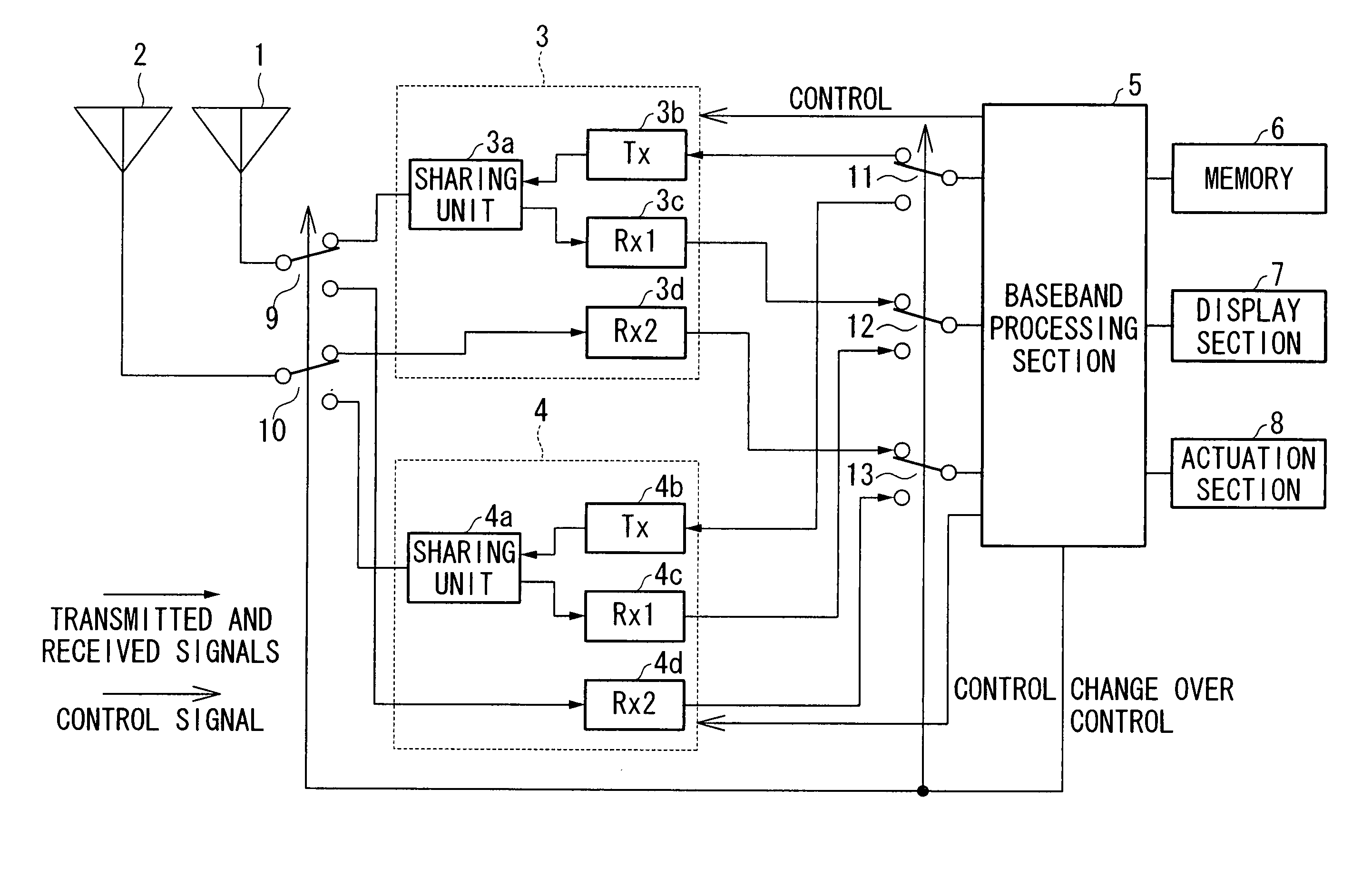
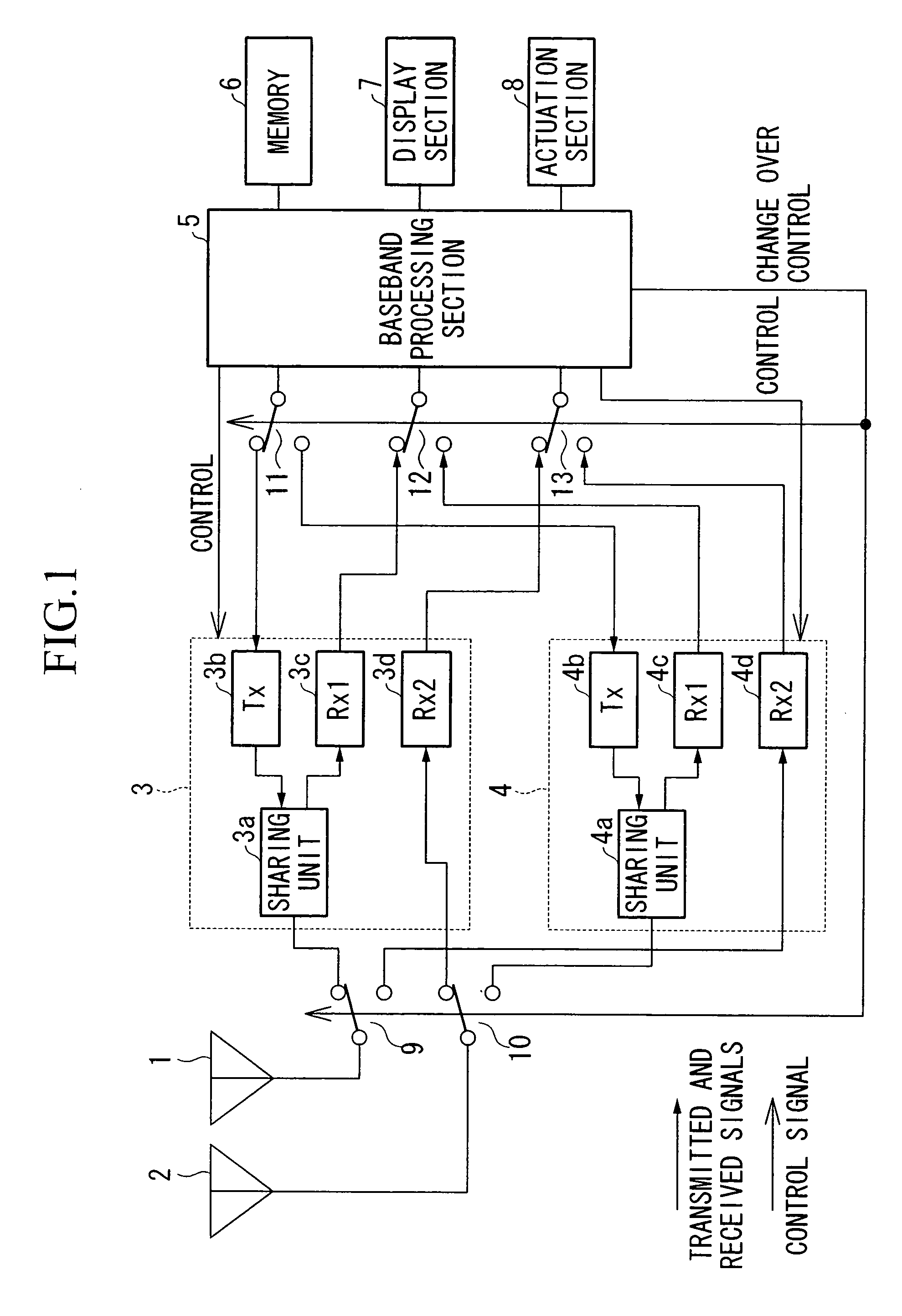
[0029] In the following, various preferred embodiments of the present invention will be explained with reference to the drawings. FIG. 1 is a block diagram showing the structure of a portable telephone unit (a wireless transmission and reception device) according to the first preferred embodiment of the present invention; the portable telephone unit shown in this figure is a portable telephone device which can perform EV-DO communication upon the 800 MHz band and EV-DO communication upon the 2 GHz band. Furthermore, the portable telephone unit performs reception processing according to a diversity method, using two antennas. In this figure, the reference symbol 1 denotes the first antenna, while the reference symbol 2 denotes the second antenna. Antennas 1 and 2 are single band antennas, and the resonant frequency of the antenna 1 is 800 MHz, while the resonant frequency of the antenna 2 is 2 GHz.

[0030] The reference symbol 3 denotes a first transmission and reception circuit which...


PUM


Abstract

An antenna control method for use in communication using a plurality of antennas which have different respective frequency bands, has a step in which, when performing transmission upon a predetermined frequency band out of the frequency bands, only an antenna which corresponds to the frequency band which is used is employed in a transmission system, and a step in which, when performing reception upon the predetermined frequency band, a diversity combination of the antenna which corresponds to the predetermined frequency band which is used and another antenna is employed in a reception system.

Description

BACKGROUND OF THE INVENTION [0001] 1. Field of the Invention [0002] The present invention relates to an antenna control method, and to a wireless transmission and reception device, which are used in a wireless communication terminal, or the like which has a reception diversity function. [0003] Priority is claimed on Japanese Patent Application No. 2004-161508, filed May 31, 2004, the content of which is incorporated herein by reference. [0004] 2. Description of Related Art [0005] With a wireless communication terminal of the cdma 2000 1x EV-DO type (hereinafter, which is termed the EV-DO type), the necessity for diversity is high, since the data rate of the downstream traffic channel is determined by the CIR (Carrier to Interference Ratio: which is also expressed as C / I) which indicates the state of reception. On the other hand, there are two wireless bands within Japan which can be used for EV-DO, one in the neighborhood of 800 MHz and another in the neighborhood of 2 GHz; but, in ...

Claims


Application Information

Patent Timeline
Patent Type & Authority Applications(United States)
IPC IPC(8): H03C7/02H04B1/00H04B1/02H04B1/18H04B1/44H04B1/707H04B7/08H04B7/12H04B7/26H04J13/00H04W16/28H04W88/02H04W88/06
CPCH04B1/0064H04B7/12H04B7/0842
Inventor KITAJI, MITSUHIROMATSUMURA, TAKASHI
Owner KYOCERA CORP
Learn More