Composite racquet with double tube head frame

a technology of double tube and composite racquet, which is applied in the field of composite racquet with double tube head frame, can solve the problems of many limitations of materials, significant weight limitations of aluminum extrusions, and differences in engineering problems associated with them, and achieves superior strength, stiffness and weight properties, and increases the effective strung area of the racquet.

Active Publication Date: 2005-12-01
EF COMPOSITE TECH
View PDF62 Cites 32 Cited by
  • Summary
  • Abstract
  • Description
  • Claims
  • Application Information

AI Technical Summary

Benefits of technology

[0006] According to one aspect of the present invention, there is provided a sports racquet with a frame that has a head portion across which strings are strung. The head portion includes an elongate upper tube which is disposed above the string bed plane and an elongate lower tube which is disposed below the string bed plane. A solid bridge of material, without any cavity in the direction of frame elongation (meaning a direction along the curved frame that is tangential to the string bed center), connects the upper tube with the lower tube and intersects the string bed plane. When a cross section is taken of the head portion, a center line can be drawn through the centers of the tubes, and the bridge is disposed to be outward of this center line so as to be relatively remote from the string bed center. This maximizes the free-space length of strings strung to the bridge.
[0008] In a third aspect of the invention, the racquet frame is made of an endless wall that in turn is made up of a plurality of laminations of fibrous material. Viewed in section, the endless wall has an outer portion that is relatively remote from the string bed center and an inner portion that is relatively proximate to the string bed center. The endless wall is used to form the upper tube, the lower tube and a single bridge between the upper and lower tubes. Along the depth of the bridge (defined as a dimension orthogonal to the string bed plane), the outer portion and inner portion of the endless wall are joined together such that there are no cavities or voids in the direction of frame elongation. Preferably, at least one lamination making a part of the endless wall is applied to the layup such that its fibers are aligned at an angle other than zero degrees (parallel to the tube axes) or ninety degrees (perpendicular to the tube axes). Since this lamination is present in both the outer portion of the endless wall and an inner portion of the endless wall, the orientation of the fibers in the lamination in the outer portion is at an angle to the orientation of the fibers in the lamination in the inner portion. This crossing of fiber direction strengthens the racquet frame.
[0011] The two-tube frame of the present invention exhibits greater strength and stiffness than a single-tube frame made with the same amount of material. Alternatively, the two-tube frame of the present invention permits a frame of similar strength and stiffness but using less material than a single-tube design of comparable strength and stiffness. The present invention exhibits far superior strength, stiffness and weight properties relative to known aluminum structures.
[0012] The use of a connecting bridge provides a structure through which single string holes can be formed instead of hole pairs through the tubes themselves (in each pair, one in the inner wall and one in the opposed, outer wall). The strength of the tubes themselves does not have to be compromised with holes. In the preferred embodiment, in which the bridge is disposed entirely outwardly of the tube center line, the length of strung string throughout the entire strung area of the racquet is maximized, optimizing the projectile-returning power of the racquet. The present invention provides a continuous channel through which each string segment passes to its connection to the bridge. Therefore, each string, even if it is strung to a point at the racquet corners, is strung in free space to a structure very close to the lateral exterior of the racquet frame, without any interference from support structures disposed interiorly of the bridge. This increases effective strung area of the racquet.
[0013] The use of composites (as herein defined to mean resin-impregnated fibrous laminations) permits substantial variation of cross section along the frame's length.

Problems solved by technology

While each succession of materials in general improved strength to weight ratios, the engineering problems associated with them differ markedly.
While forming racquet frames from extruded aluminum alloys is relatively cheap because of lower labor costs, the material has many limitations.
Aluminum extrusions have substantial weight limitations.
While there have been multiple-tube composite structures, it has been found that any internal divisions, bridges or lumens placed in these tubes are difficult to control in their placement because of variations in bladder air pressure, and attempts to include them in the past have been found to cause significant quality control and production problems.

Method used


Image

  • Composite racquet with double tube head frame
  • Composite racquet with double tube head frame
  • Composite racquet with double tube head frame

Examples


examples

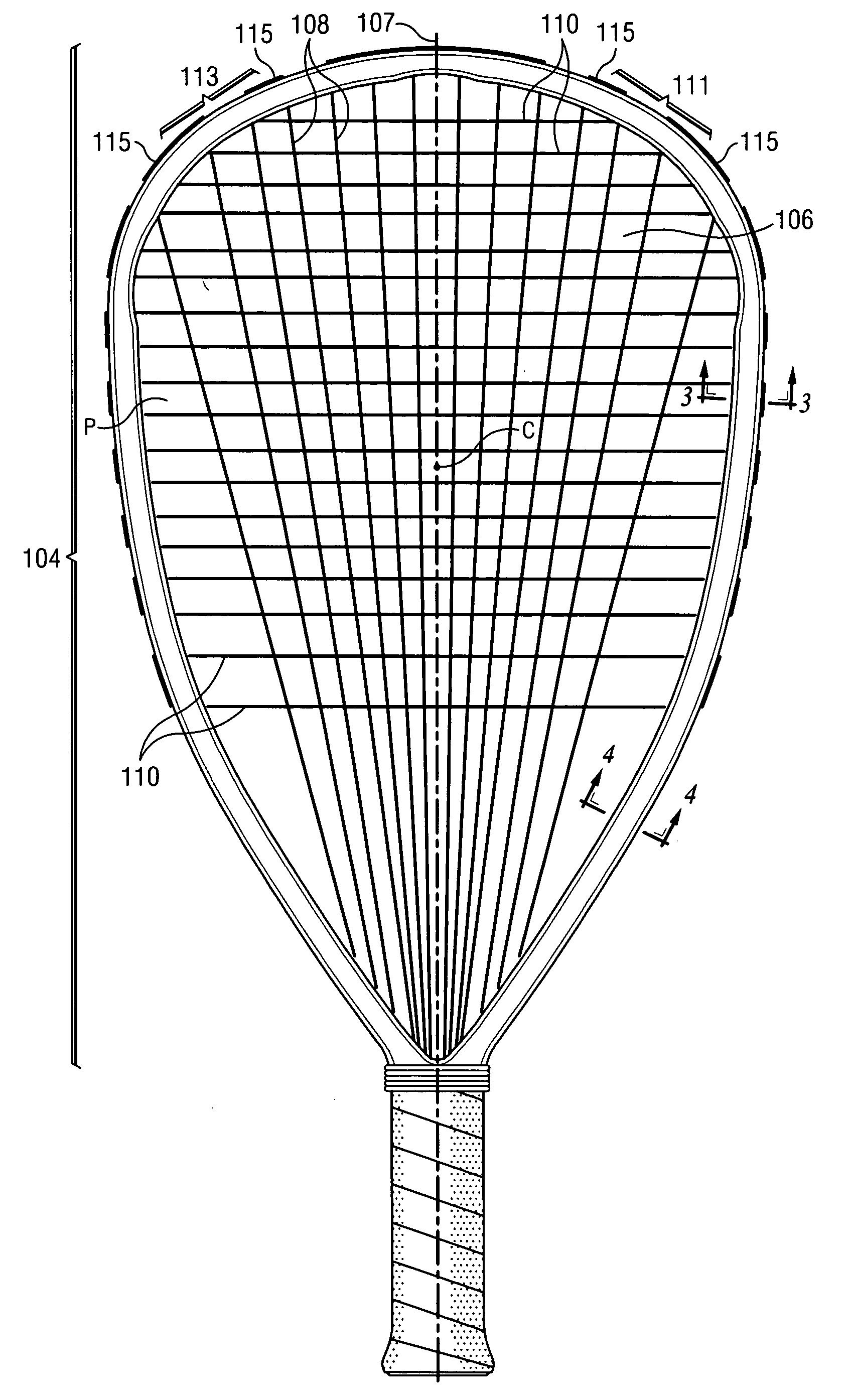
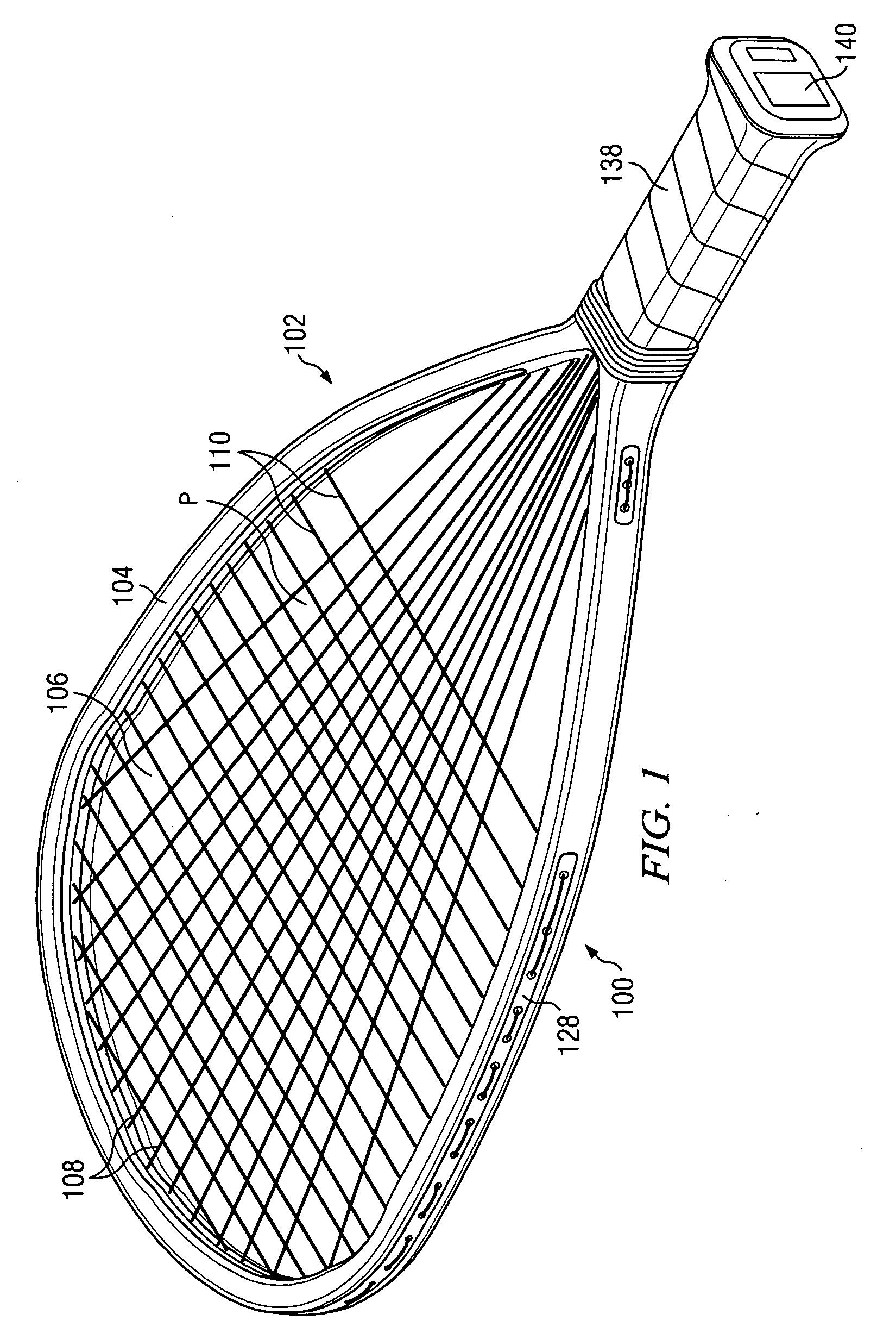
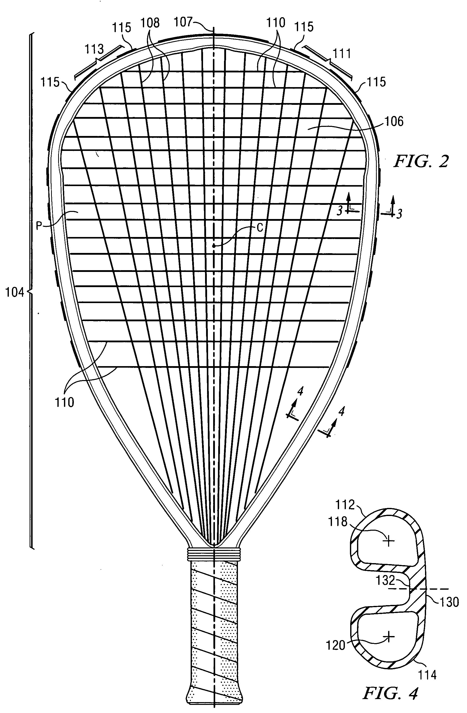
[0069] To demonstrate the technical advantages of the structure of the present invention over prior art and other structures, a series of tests was performed on a racquet according to the invention and having the morphology shown in FIGS. 1-4, and also on other racquet structures. FIGS. 8, 9 and 10A-10D are representative cross-sectional views of these other tested structures.

[0070]FIG. 8 is a cross-sectional view of a prior art composite racquetball racquet frame. This cross section is basically an oval 200 with an indentation on one side. “Traditional oval” racquet 202 was constructed of composite materials similar to those used in the present invention and substantially the same as those in the sample according to the invention that was tested herein.

[0071]FIG. 9 is a cross-sectional view of a prior art aluminum racquetball racquet frame 204. “Aluminum traditional oval” frame 204 has a pair of internal supports 206, 208 for purposes of stiffening. The control of the placement o...


PUM


Abstract

A sports racquet frame is built of a composite of laminations of fibrous material as impregnated by a thermosetting resin. The head section of the frame has an upper tube preferably disposed above the string bed plane and a lower tube preferably disposed below the string bed plane. A solid bridge of material integrally joins the upper tube to the lower tube. In a preferred embodiment the bridge is disposed radially exteriorly of the center line of the tubes, to maximize the length of string segments, which are strung to the bridge.

Description

BACKGROUND OF THE INVENTION [0001] Sports racquets, which term includes tennis rackets, squash racquets, badminton racquets and racquetball racquets, are all strung with strings across a head portion of a frame, which head portion surrounds and defines a string bed. The string bed is designed to intercept and return a game piece such as a shuttlecock, racquetball or tennis ball. [0002] Up into the 1960's sports racquets were made of wood. These racquets were replaced with racquets made of metal, typically of aluminum alloy, although steel has also been used. In the 1970's thermoplastic injection molded racquets were attempted, as reinforced with fiber whiskers. Also in the 1970's sports racquets began to be made from a composite material which has as its basic constituents (a) plural laminations of fibrous material such as carbon fiber, boron, fiberglass and / or aramid compositions, and (b) a binding thermosetting resin. While each succession of materials in general improved strength...

Claims


Application Information

Patent Timeline
Patent Type & Authority Applications(United States)
IPC IPC(8): A63B49/02A63B49/10A63B51/00
CPCA63B49/007A63B2209/02A63B49/106A63B49/02A63B49/022A63B49/028A63B49/11A63B49/10
Inventor FILIPPINI, RAFAEL G.
Owner EF COMPOSITE TECH
Why Eureka
Try Eureka