
Portable device for monitoring electrocardiographic signals and indices of blood flow

Active Publication Date: 2005-12-01
RGT UNIV OF MINNESOTA
View PDF32 Cites 90 Cited by
  • Summary
  • Abstract
  • Description
  • Claims
  • Application Information

AI Technical Summary

Benefits of technology

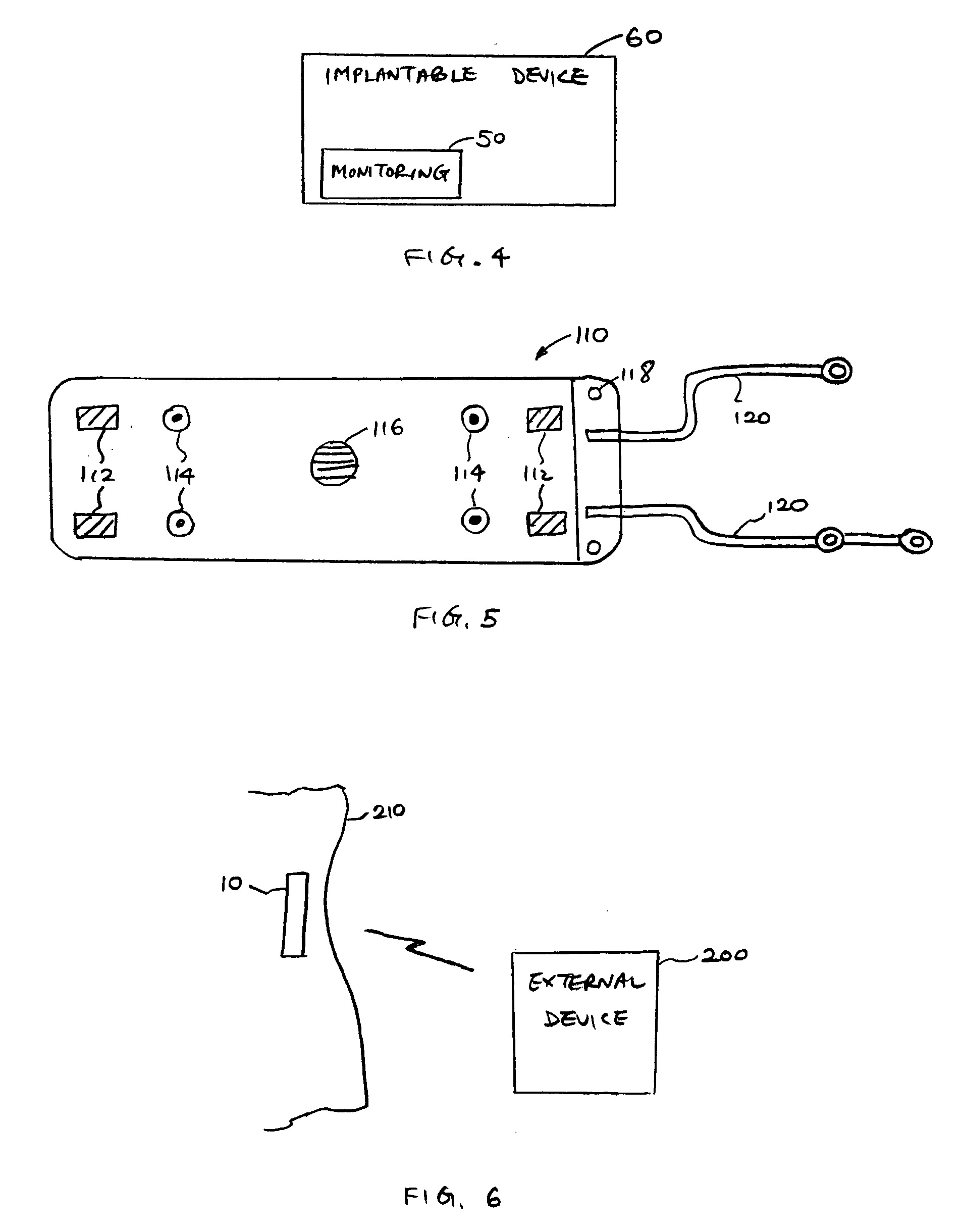
[0006] Embodiments of the present invention are directed to a physiological monitoring device which is configured to record signals that reflect blood flow and / or blood pressure, and which may also record ECG signals. In an exemplary embodiment, a portable diagnostic monitoring device is capable of detecting abnormal cardiac rhythms and assess their impact on blood flow, as well as detect abnormalities of blood flow that may or may not be associated with an abnormal heart rhythm. An example of clinical use is the evaluation of individuals experiencing syncope (faints) of unknown origin. The monitoring device may be worn on the body surface of the patient. A more practical embodiment of the monitoring device is of a sufficiently small size as to be insertable into the body of the patient using techniques essentially identical to placement of a conventional pacemaker generator. In the exemplary embodiment, intra-vascular access is not utilized, so that the system offers diagnostic capabilities without invading blood vessels to insert sensors. In other embodiments, intravascular or extravascular leads may be used to enhance the diagnostic capability. In yet other embodiments, the monitoring device may be incorporated into a conventional pacemaker or implantable defibrillator (ICD) to enhance the diagnostic capability of those instruments.

Problems solved by technology

In these conditions the heart rhythm may remain normal, or only relatively minor abnormalities are recorded and the heart rate may remain within the normal range; nonetheless, the blood pressure becomes abnormally low.
Currently, these latter conditions are difficult to document in free-living individuals as they occur unpredictably over time, and at present there is no available portable monitor systems which can document both ECG and hemodynamic alterations over relatively long periods (e.g., weeks or months).

Method used


Image

  • Portable device for monitoring electrocardiographic signals and indices of blood flow
  • Portable device for monitoring electrocardiographic signals and indices of blood flow
  • Portable device for monitoring electrocardiographic signals and indices of blood flow

Examples


Embodiment Construction

[0022] The following detailed description should be read with reference to the drawings in which similar elements in different drawings are numbered the same. The drawings, which are not necessarily to scale, depict illustrative embodiments and are not intended to limit the scope of the invention.

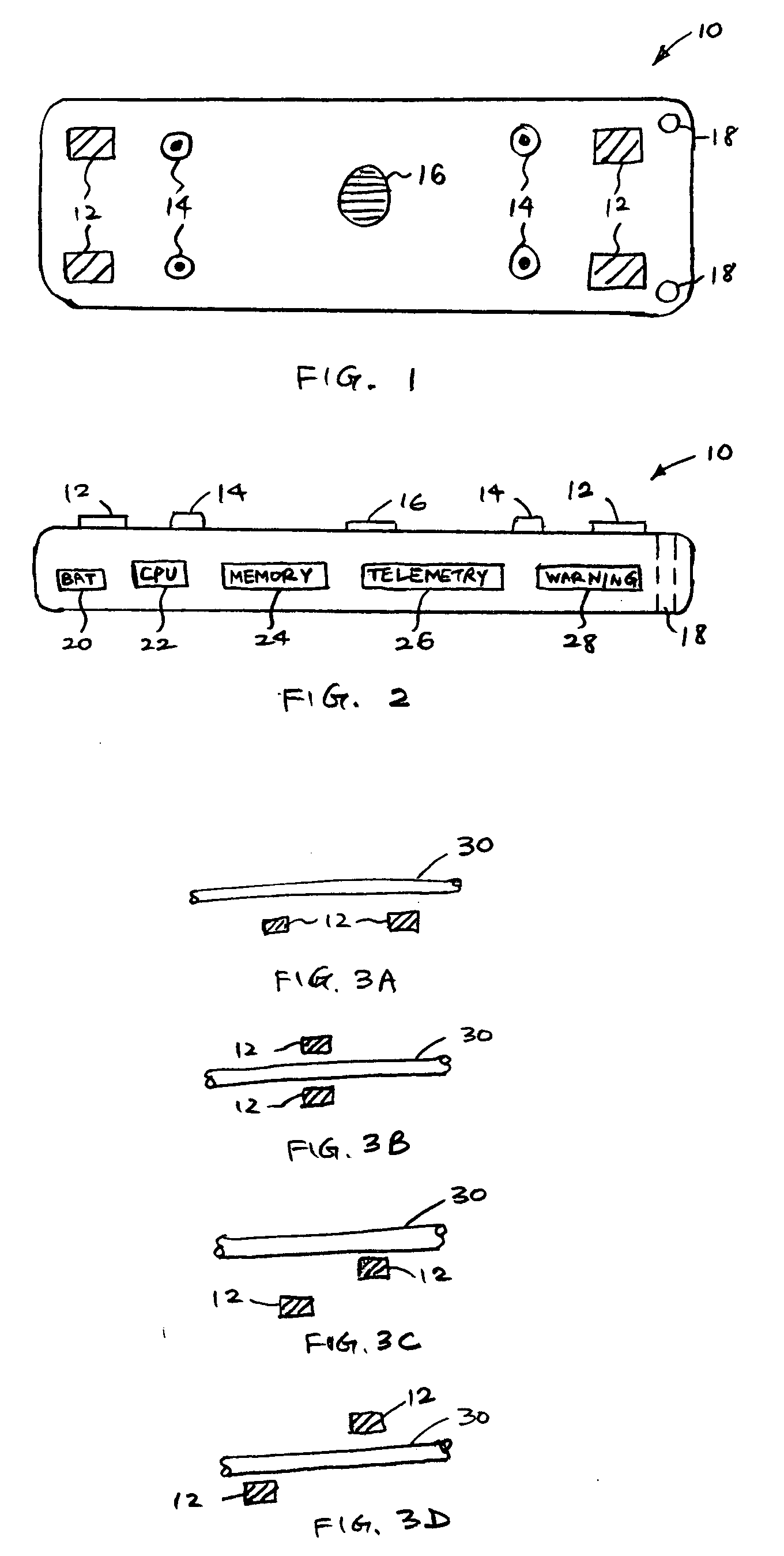
[0023]FIGS. 1 and 2 show a monitoring device 10 which includes a plurality of impedance electrodes 12, a plurality of ECG electrodes 14, a temperature sensor 16, and a plurality of suture ports 18. FIGS. 1 and 2 show four impedance electrodes 12 that are spaced from each other and four ECG electrodes 14 that are spaced from each other, although fewer (e.g., two impedance electrodes and two ECG electrodes) or more electrodes may be used in other embodiments. The use of four impedance electrodes 12 can eliminate electrode interface artifacts and the high electrode tissue impedance. The sensors and electrodes are depicted as protruding from the surface, but they may be flat. In the specific e...


PUM


Abstract

Embodiments of the present invention are directed to a physiological monitoring device which is configured to record signals that reflect blood flow and / or blood pressure, and which may also record ECG signals. In one embodiment, a portable monitoring device comprises a plurality of impedance electrodes configured to be coupled to a patient's body and to generate an AC current with an electrical field to detect local electrical impedance of a portion of the patient's body encompassed by the electrical field, the local electrical impedance being a surrogate measure of local blood flow of the portion of the patient's body. At least a portion of the portable monitoring device is configured to be insertable subcutaneously into the patient's body.

Description

CROSS-REFERENCES TO RELATED APPLICATIONS [0001] This application is based on and claims the benefit of U.S. Provisional Patent Application No. 60 / 569,551, filed May 10, 2004, the entire disclosure of which is incorporated herein by reference.BACKGROUND OF THE INVENTION [0002] The present invention relates to diagnostic monitoring systems and, more particularly, to a portable diagnostic monitoring system for assessing cardiovascular hemodynamic state during the setting of a normal or abnormal heart rhythm. Advantageously, the monitoring system is capable of detecting abnormalities of blood pressure and / or flow. [0003] Changes in cardiac output or blood pressure may be of value in diagnosis and management chronic and / or recurring disease states (e.g., congestive heart failure, hypertension, syncope). Currently, such measurements require invasive intravascular catheters with attached sensors (e.g., pressure, oxygen saturation) or an intra-arterial cannula. [0004] Devices employing the ...

Claims


Application Information

Patent Timeline
IPC IPC(8): A61B5/00A61B5/02A61B5/0205A61B5/021A61B5/026A61B5/363
CPCA61B5/0031A61B5/02028A61B5/02055A61B5/6837A61B5/026A61B5/0464A61B5/0535A61B5/021A61B5/0295A61B5/363
Inventor BENDITT, DAVIDPATTERSON, ROBERTLURIE, KEITH G.
Owner RGT UNIV OF MINNESOTA
Learn More