

Split-cycle four-stroke engine
a four-stroke, split-cycle technology, applied in the direction of machines/engines, mechanical equipment, transportation and packaging, etc., to achieve the effect of greater efficiency and performan
- Summary
- Abstract
- Description
- Claims
- Application Information
AI Technical Summary
Benefits of technology
Problems solved by technology
Method used
Image

Examples
Embodiment Construction
I. Overview
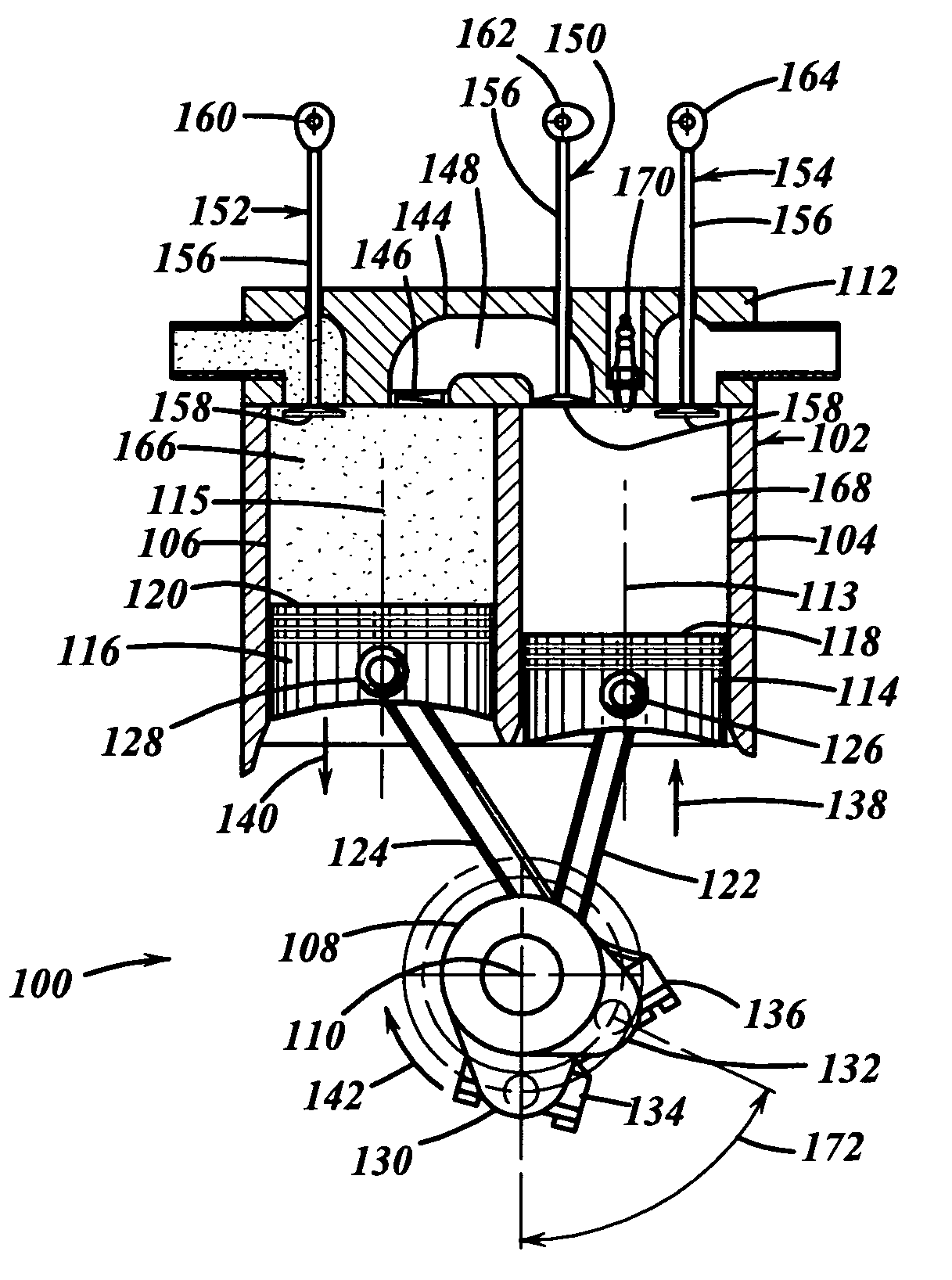
[0053] The Scuderi Group, LLC commissioned the Southwest Research Institute® (SwRI®) of San Antonio, Tex. to perform a Computerized Study. The Computerized Study involved constructing a computerized model that represented various embodiments of a split-cycle engine, which was compared to a computerized model of a conventional four stroke internal combustion engine having the same trapped mass per cycle. The Study's final report (SwRI® Project No. 03.05932, dated Jun. 24, 2003, titled “Evaluation Of Split-Cycle Four-Stroke Engine Concept”) is herein incorporated by reference in its entirety. The Computerized Study resulted in the present invention described herein through exemplary embodiments pertaining to a split-cycle engine.
II. Glossary
The following glossary of acronyms and definitions of terms used herein is provided for reference:
[0054] Air / fuel Ratio: proportion of air to fuel in the intake charge [0055] Bottom Dead Center (BDC): the piston's farthest position f...
PUM
 Abstract
Description
Claims
Application Information