
Simulated moving bed separation process and device

Inactive Publication Date: 2005-12-08
INST FR DU PETROLE
View PDF4 Cites 21 Cited by
  • Summary
  • Abstract
  • Description
  • Claims
  • Application Information

AI Technical Summary

Benefits of technology

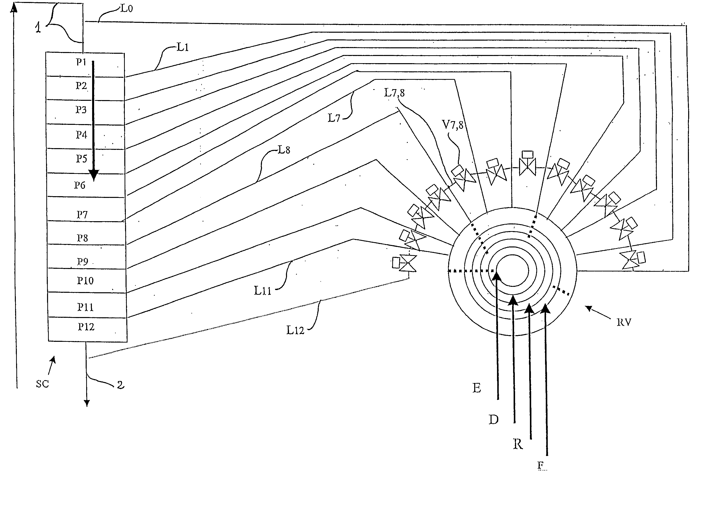
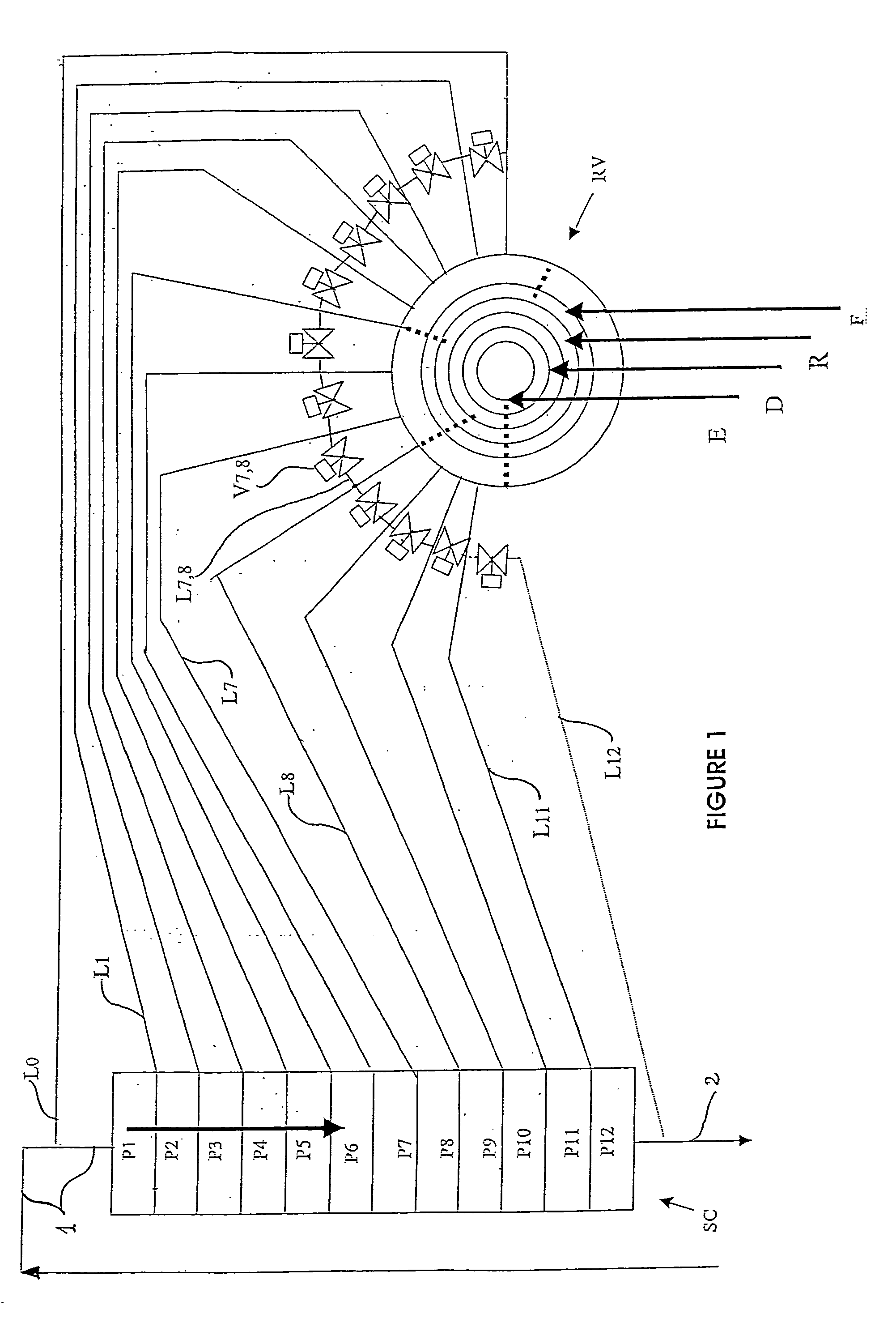
[0040] An essential element of the device according to the invention consists of installing, around a multi-way rotary valve, a plurality of bypass lines between adjacent outlets, which are joined two by two, for the implementation of lengthy flushing currents with a small or zero concentration gradient. These bypass lines are typically installed in immediate proximity to the rotary valve, such that most of the junction lines between the valve and the trays are flushed. This makes it possible to obtain a very effective flushing of the dead zones and to avoid internal recirculations.

Problems solved by technology

A generic problem of all SMB devices is the minimizing of the pollution generated by the liquid situated in the different zones and volumes of the circuits for the feeding and drawing off of fluids, chambers Ci, and in the DMEs, during modifications of the feed and drawing-off points during the operation of the SMB.
Another problem can lie in any recirculations between different zones of the same tray, which then also gives rise to a disturbance vis-à-vis ideal operation.
In fact, there are different embodiments which can lead to different dead volumes, with symmetrical or asymmetrical feeds, which in the latter case gives rise to increased risks of internal recirculations inside the same tray.
However, as the flushing liquid typically has a very different composition from the liquid that it displaces, this introduces discontinuities of composition detrimental to ideal operation.
However, it is not totally satisfactory as it requires the making of a special multi-way valve, different from and more complex than the conventional multi-way valve which is designed without continuous (or lengthy) internal bypasses.

Method used


Image

  • Simulated moving bed separation process and device
  • Simulated moving bed separation process and device
  • Simulated moving bed separation process and device

Examples


Embodiment Construction

[0044] The invention therefore presents a simulated moving bed separation device and process.

[0045] It relates in particular to a device permitting the separation of at least one sought compound from a mixture containing this compound, by adsorption on a simulated moving bed comprising: [0046] at least one enclosure or column, comprising a plurality of beds of adsorbents (Ai), two consecutive beds of adsorbents being separated by at least one tray (Pi) for collection / redistribution of the principal fluid and injection / extraction of secondary process fluids, the tray comprising one or more distribution / extraction / mixing, or “DME” panels, permitting the distribution, extraction and / or mixing of these fluids, [0047] at least one multi-way rotary valve (RV), [0048] a plurality of conduits Li (L1 . . . . L7, L8, . . . . L11, L12 . . . ) linking said multi-way rotary valve to said trays Pi, [0049] for at least some (often more than 50%) of the conduits Li (for example L7 or L8), means fo...


PUM

PropertyMeasurementUnit
Fractionaaaaaaaaaa
Fractionaaaaaaaaaa
Fractionaaaaaaaaaa

Abstract

A simulated moving bed separation device is described, comprising at least one column, beds of adsorbent arranged in this column, trays Pi with a chamber Ci for distribution and extraction of fluids, a multi-way rotary valve for the distribution of the fluids feeding or leaving said trays, and junction lines Li between this valve and said trays. The device according to the invention also comprises a plurality of bypass lines Li,i+1 between adjacent lines, these bypasses being outside the multi-way rotary valve and situated in proximity to this valve, for the circulation of rinsing liquids with a small or zero concentration gradient. The invention makes it possible to use all types of distribution and extraction trays and all types of adsorbent loading, whilst preserving a high level of product purity. Application to the separation process in particular of paraxylene or metaxylene from a C8 aromatic charge.

Description

FIELD OF THE INVENTION [0001] The invention relates to the field of separations of natural or chemical products which are difficult to separate by distillation. A family of processes and associated devices is used, known by the name of “chromatographic”, or “simulated moving bed”, or “simulated counter-current” separation processes or devices, which we will call “SMB” (Simulated Moving Bed) hereafter. [0002] The fields concerned are in particular, and non-exclusively: [0003] separation between normal paraffins on the one hand and branched paraffins, naphthenes and aromatics on the other hand, [0004] olefins / paraffins separation, [0005] separation of paraxylene from the other C8 aromatic isomers, [0006] separation of metaxylene from the other C8 aromatic isomers, [0007] separation of ethylbenzene from the other C8 aromatic isomers. Outside the refinery and petrochemical complex, there are numerous other uses among which there can be mentioned glucose / fructose separation, the separat...

Claims


Application Information

Patent Timeline
IPC IPC(8): B01D15/18C07C7/12C07C7/171
CPCB01D15/1871B01D53/0423B01D2259/40005Y10T436/11C07C7/12B01D2259/4146C07C15/08B01D15/08B01D15/00
Inventor HOTIER, GERARD
Owner INST FR DU PETROLE
Learn More