Fuel injection valve

a fuel injection valve and valve body technology, applied in the direction of valve operating means/release devices, machines/engines, mechanical equipment, etc., can solve the problems of fuel injection that cannot be controlled and irreproducible, the bouncing of the movable core and the valve body, and the variation of the opening and closing time of the injection nozzle, so as to reduce the bouncing of the movable core and the valve body, and increase the minimum number of components. the effect of simple construction

Inactive Publication Date: 2005-12-08
DENSO CORP
View PDF8 Cites 12 Cited by
  • Summary
  • Abstract
  • Description
  • Claims
  • Application Information

AI Technical Summary

Benefits of technology

[0007] Accordingly, an object of the present invention is to provide an injector which uses a simple construction to reduce bouncing of the movable core and the valve member, with increasing the minimum number of components, and which displays little variation in fuel injection characteristics over its lifetime.

Problems solved by technology

As a result, the impact of the collisions causes so-called bouncing of the movable core and the valve member.
In an injector, bouncing of the valve member results in variation of opening time and closing time of the injection nozzle.
This results in uncontrollable and irreproducible injection of fuel from the injection nozzle.
The effect of bouncing is particularly marked when the length of the energizing pulse applied to the coil is small, making it impossible to precisely control the amount of fuel injected and the shape of the fuel spray.
This leads to a more complicated construction and increases the some number of components.
Furthermore, long term operation of the injector can cause spring fatigue and abrasion and the like.
Consequently, the characteristics of the springs vary over time, and it is difficult to ensure stable fuel injection characteristics over an extended period.

Method used


Image

  • Fuel injection valve
  • Fuel injection valve
  • Fuel injection valve

Examples


first embodiment

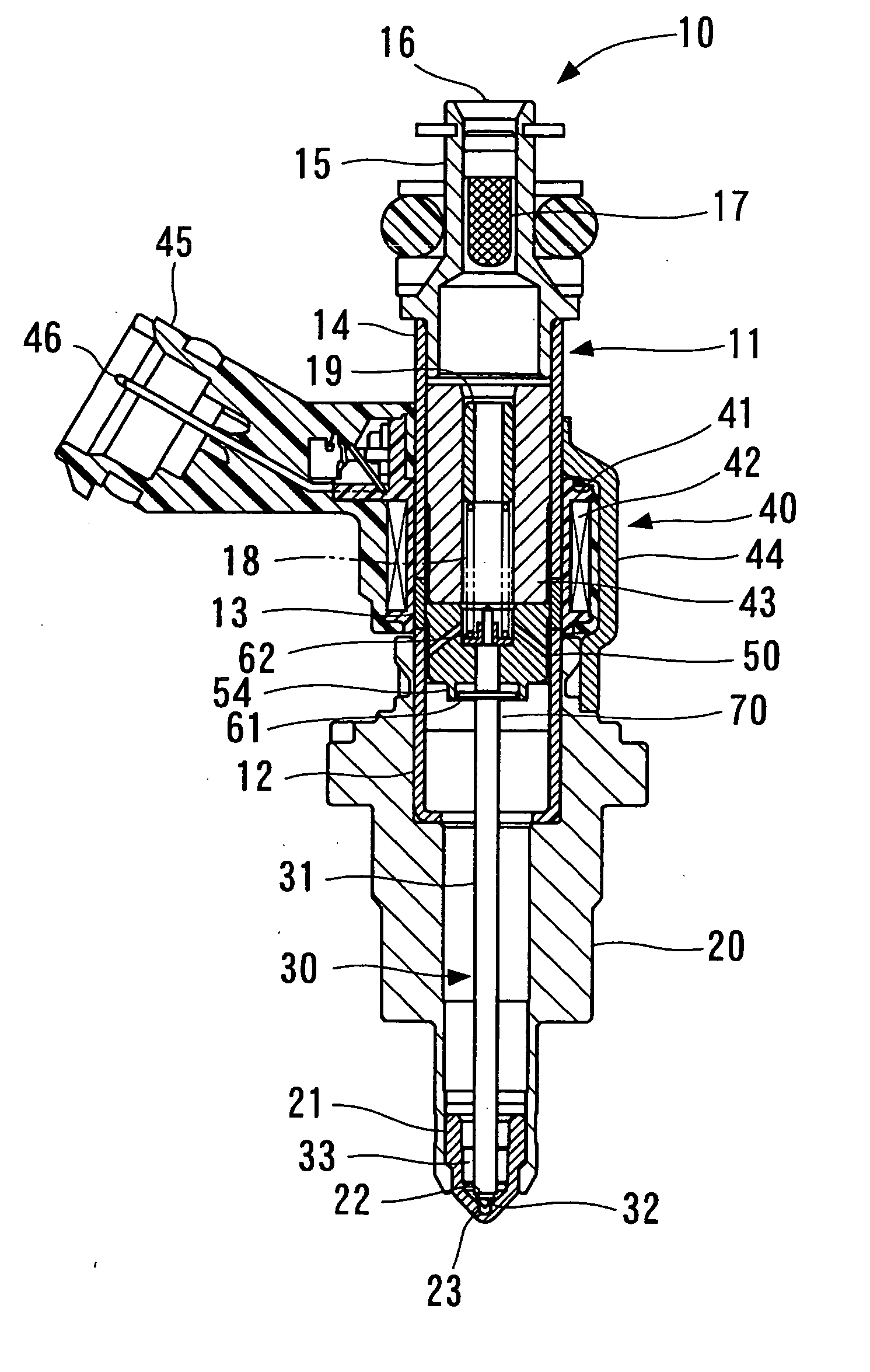
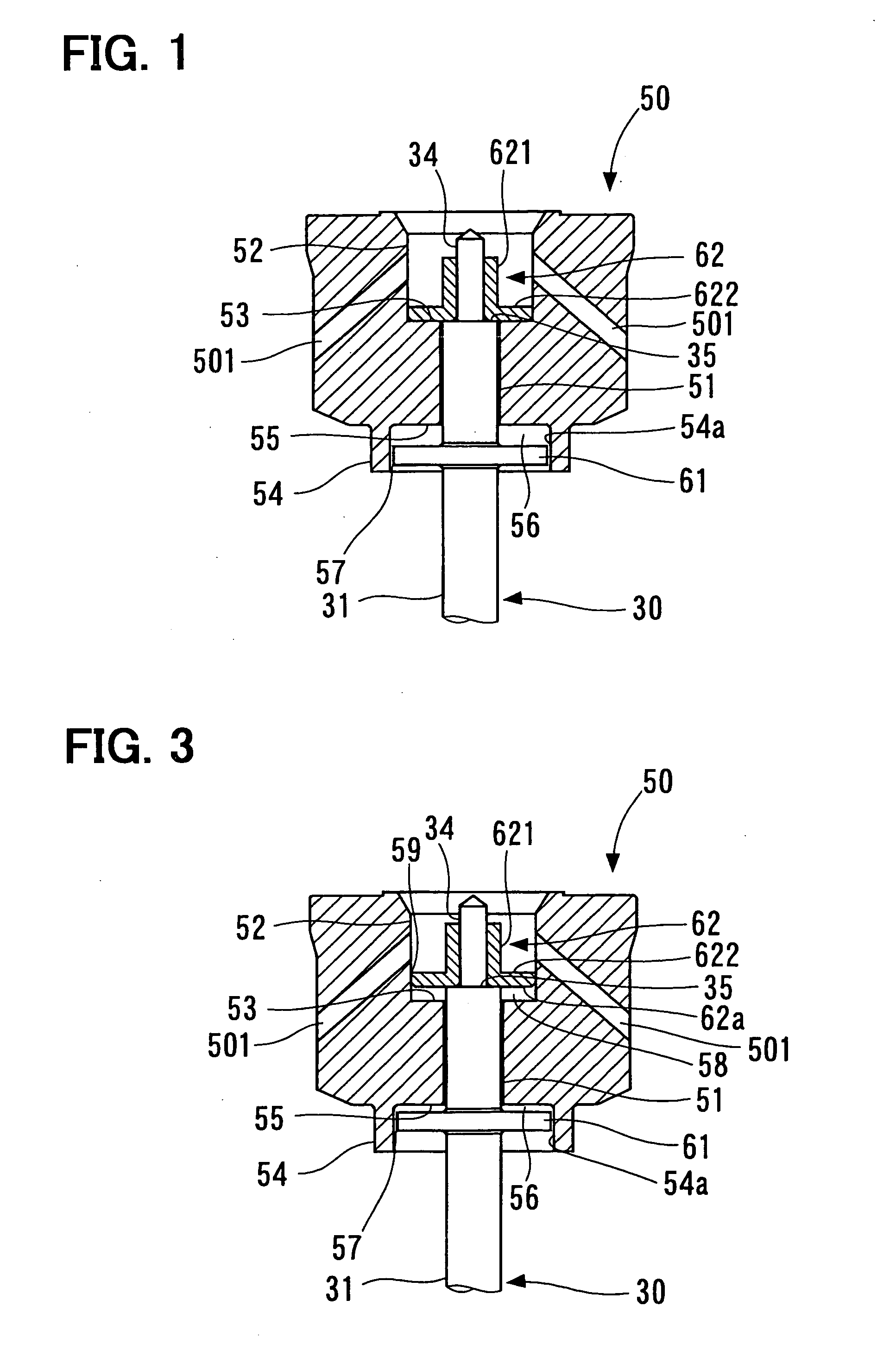
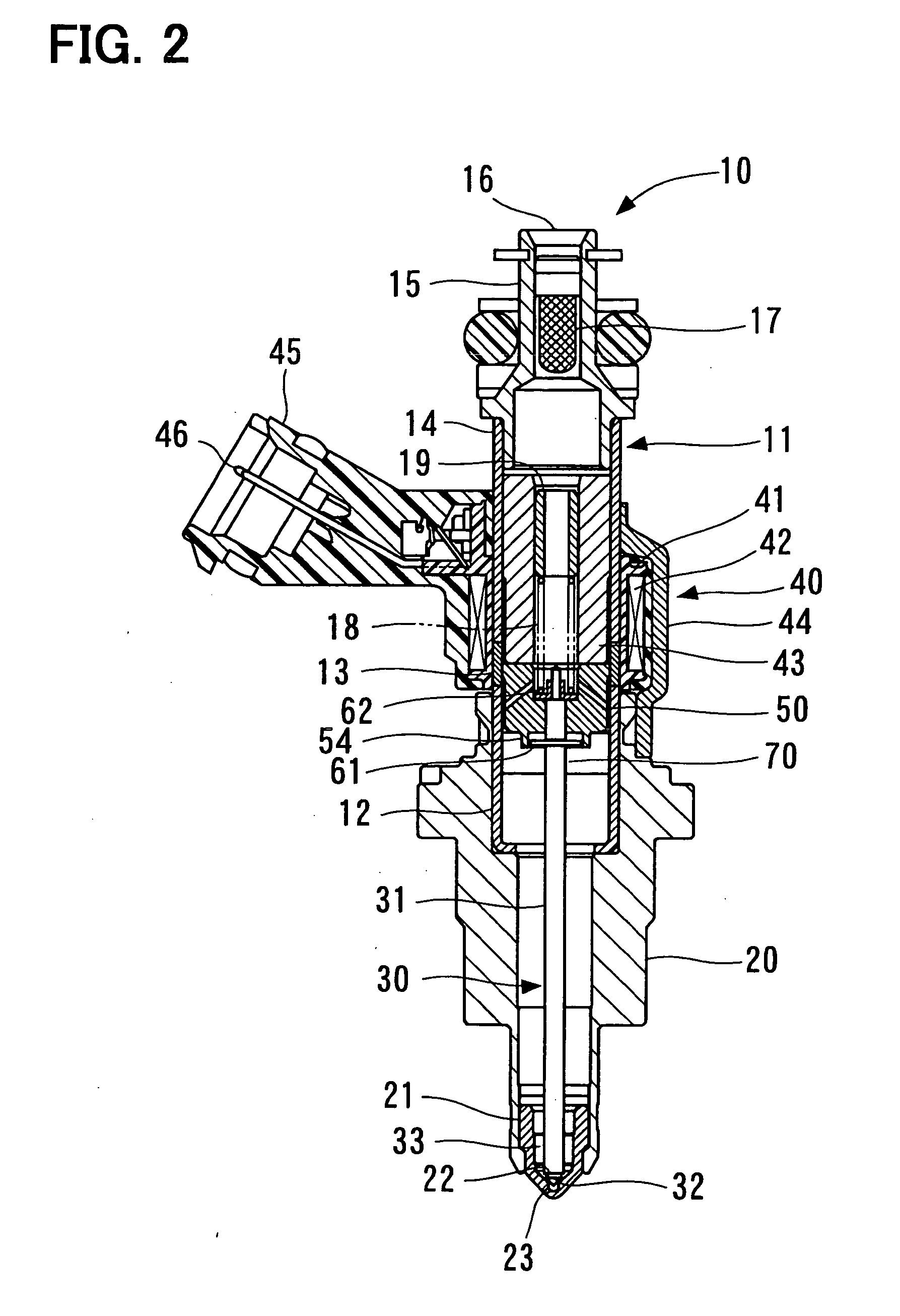
[0064] As described above, in the first embodiment, the movable core 50 and the needle 30 are freely movable relative to each other over a predetermined range in the axial direction. Consequently, bouncing of the movable core 50, which occurs when the fixed core 43 and the movable core 50 collide, is absorbed by the inertial movement of the needle 30 in the direction opposite to the bouncing. Furthermore, bouncing of the needle 30, which occurs when the needle 30 collides with the valve seat 22, is absorbed by the inertial movement of the movable core 50 in the direction opposite to the bouncing. In addition, the relative movement between the needle 30 and the movable core 50 is moderated by the damping effect of the fuel in the fuel chambers 56 and 58 formed between the first stop member 61 or the second stop member 62 respectively, and the movable core 50. Thus, the impact of a collision is moderated, while still ensuring that the needle 30 and the movable core 50 move as a unit. ...

second embodiment

[0072] As shown in FIG. 6, a movable core 70 of the injector has a recess 71 at the opposite end from the fixed core 43. The recess 71 is recessed towards the fixed core 43. This recess 71 corresponds to the injection side recess in the claims. The inside diameter of the recess 71 is greater than that of a hole portion 72. Consequently, a stepped portion 73 is formed between the recess 71 and the hole portion 72. Furthermore, the movable core 70 comprises fuel passages 701 which connect the inside of the movable core 70 with the outside.

[0073] During relative movement of the needle 30 and the movable core 70 in the axial direction, the first stop member 61, which is integrated with the needle 30, moves axially back and forth inside the recess 71. Consequently, a fuel chamber 74 is formed between the stepped portion 73 of the movable core 70, the inner circumferential surface of the movable core 70 that forms the recess 71, and the surface of the first stop member 61 on the side of ...

third embodiment

[0076] As shown in FIG. 7, in a movable core 80 a groove 81 is formed in the end portion at the opposite side from the fixed core 43. The groove 81 is recessed into the movable core 80 in the direction of the fixed core 43. The groove 81 is formed as a continuous ring shape, around the circumferential direction of the movable core 80. Furthermore, a first stop member 90 provided on the needle 30 comprises an inner cylinder portion 91, which is press-fit onto the needle 30, an expansion portion 92, which protrudes radially outward from the inner cylinder portion 91, and an outer cylinder portion 93, which rises from the radial outside edge of the expansion portion 92, towards the fixed core 43 side. The outer cylinder portion 93 is designed to enter the groove 81 of the movable core 80, leaving a slight gap. The movable core 80 comprises fuel passages 801 which connect the inside of the movable core 80 with the outside.

[0077] By employing the above construction, a first fuel chamber...


PUM


Abstract

A fuel injection valve includes a valve member, a first stop member, a second stop member, a movable core, a fixed core, and a coil. The valve member opens and closes an injection nozzle. The first stop member protrudes radially outward from said valve member. The second stop member protrudes radially outward from said valve member. The movable core is sandwiched between said first and second stop members. The movable core and one of said first and second stop members defines a fuel chamber. The fixed core is axially displaced from said movable core. The coil causes reciprocal axial displacement of said valve member such that said movable core axially reciprocates toward and away from said fixed core therewith.

Description

CROSS REFERENCE TO RELATED APPLICATIONS [0001] This application is based upon and claims the benefit of priority of Japanese Patent Application No. 2004-164359, filed on Jun. 2, 2004 and Japanese Patent Application No. 2005-41934, filed on Feb. 18, 2005, the contents of which are incorporated herein by reference. FIELD OF THE INVENTION [0002] The present invention relates to a fuel injection valve and, more particularly, a fuel injection valve having a movable core. BACKGROUND OF THE INVENTION [0003] In a conventional type of injector, a valve member formed as an integral part of a movable core is driven using magnetic attraction generated between a fixed core and the movable core in response to energization of a coil. In such an injector, the valve member moves back and forth in the axial direction according to whether or not the coil is energized. Consequently, when the movable core moves towards the fixed core, it collides with the fixed core, whereas when the movable core moves ...

Claims


Application Information

Patent Timeline
Patent Type & Authority Applications(United States)
IPC IPC(8): F02M51/06F02M63/00
CPCF02M51/0685F02M2200/304
Inventor NISHIWAKI, TOYOJI
Owner DENSO CORP
Why Eureka
Try Eureka