Vibration reducer and switching device

A technology of shock absorber and pressure relief device, which is applied in the direction of shock absorber, shock absorber, spring/shock absorber, etc., to achieve the effect of convenient adjustment operation, optimization of dynamic performance and improvement of dynamic performance

Inactive Publication Date: 2016-02-24
陈鸽
View PDF5 Cites 8 Cited by
  • Summary
  • Abstract
  • Description
  • Claims
  • Application Information

AI Technical Summary

Problems solved by technology

These measures have greatly improved the opening and closing movement performance of the high and low voltage mechanical switches, b...

Method used


Image

  • Vibration reducer and switching device
  • Vibration reducer and switching device
  • Vibration reducer and switching device

Examples


Embodiment approach 1

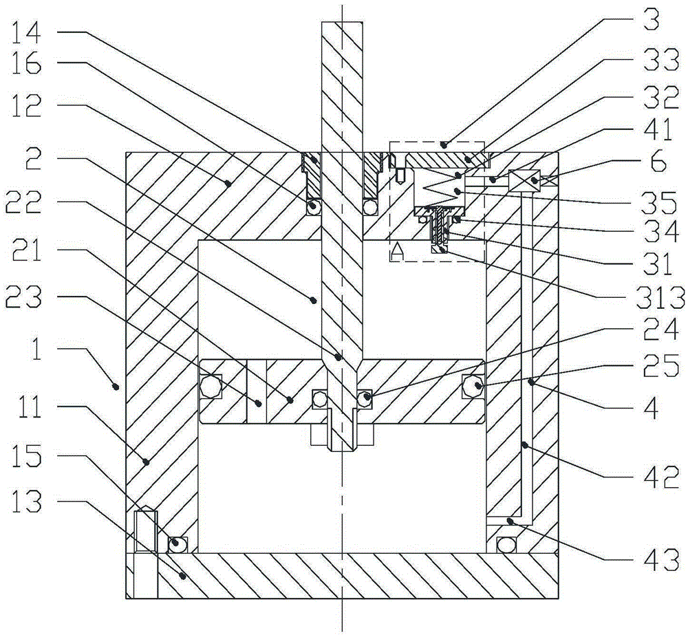
[0045] A shock absorber of the present invention, such as figure 1As shown, it includes a cylinder 1, a piston mechanism 2, a pressure relief device 3, a channel 4 and a regulating valve 6. The cylinder body 1 includes a first end cover 12, a cylinder barrel 11 and a second end cover 13, the first end cover 12 is sealed and fixed on the top end of the cylinder barrel 1, further, the first end cover 12 and the cylinder The barrel 1 is integrally formed; the second end cover 13 is fixed on the bottom end of the cylinder barrel 1 by bolts, and the second end cover 13 and the bottom end of the cylinder barrel 1 are sealed by the first sealing ring 15 . The piston mechanism 2 includes a piston 21 and a piston rod 22 . The piston 21 is arranged inside the cylinder 1 , and the side surface of the piston 21 and the inner surface of the cylinder 11 are sealed by a fourth sealing ring 25 , and the piston 21 can slide relative to the cylinder 11 along the axial direction. The piston 21...

Embodiment approach 2

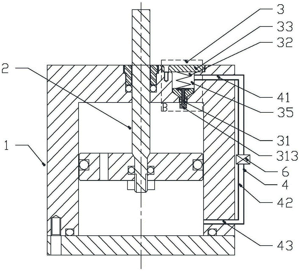
[0056] The difference between Embodiment 2 and Embodiment 1 is only: figure 2 As shown, the channel 4 includes a first channel 41 , a second channel 42 and a third channel 43 . The first channel 41 is built in the first end cover 12 and is in sealing communication with the pressure relief chamber 35 of the pressure relief device, distributed along the radial direction of the first end cover 12; the second channel 42 is arranged outside the cylinder 1, Distributed along the axial direction of the cylinder 11; the third channel 43 is arranged in the cylinder wall of the cylinder 11 and is located on the side of the second end cover 13 and is in sealing communication with the second chamber, distributed along the radial direction of the cylinder 11 . The first channel 41 , the second channel 42 and the third channel 43 are sequentially connected in a sealed manner, and the regulating valve 6 is arranged on the second channel 42 and communicated with it in a sealed manner.

Embodiment approach 3

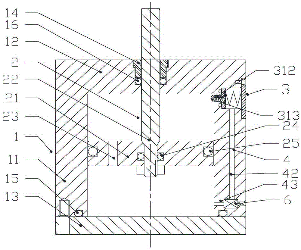
[0058] The difference between Embodiment 3 and Embodiment 1 is only: image 3 As shown, the pressure relief device 3 is assembled on the upper end of the cylinder wall of the cylinder 11 , that is, on the side of the first end cover 12 . The pressure relief chamber 35 of the pressure relief device 3 is arranged on the upper end of the cylinder wall of the cylinder 11, which is composed of a bottom wall and a side wall, and the top opening is opened at the outer end of the cylinder 11. Here, the pressure relief device 3 The axis direction determines the top and bottom of the spatial orientation of the pressure relief device 3 . The end of the stem of the pressure relief valve core 31 is inside the valve seat hole 37 , that is, the end of the stem of the valve core does not protrude from the inner surface of the cylinder 11 . The built-in telescopic rod 313 of the pressure relief valve core 31 extends into the cylinder body 1. The part is a spherical crown, and can also be incl...


PUM


Abstract

The invention discloses a vibration reducer and a switching device. The vibration reducer comprises a cylinder, a piston, a piston rod and a pressure relieving device, wherein one end of the piston rod penetrates through a first end cover, and extends into the cylinder to be fixed with the piston in the cylinder; a cavity of the cylinder is divided into a first cavity and a second cavity at the sides of the first end cover by the piston; the pressure relieving device is assembled on the cylinder, and a valve core rod part of a pressure relieving valve rod in the pressure relieving device extends into the first cavity; an extension rod is positioned in the pressure relieving valve core for adjusting a pressure relieving trigger travel; a first limiting mechanism is arranged between the extension rod and the pressure relieving valve core; and the pressure relieving device and the second cavity are communicated through a channel provided with an adjusting valve. The switching device comprises a single-pole switch; the single-pole switch is axially connected with the vibration reducer; when the switch is switched on, the damping is relieved at the tail section of the moving contact travel, so that the switching-on bounce of a moving contact of the switching device accelerated by the damping force is prevented, and the switching-on time is shortened; the damping releasing strength is adjusted; and the vibration reducer and the switching device are in synergistic effect to optimize the switching-on performance.

Description

technical field [0001] The present invention relates to a shock absorber, in particular to a shock absorber that generates damping at the front end of the stroke and releases damping at the end of the stroke, and releases the damping. The utility model relates to a switch device of a device, which belongs to the field of vibration damping equipment. Background technique [0002] At present, new and higher requirements are continuously put forward for the opening and closing performance of high-voltage and low-voltage mechanical switches, and the opening and closing time is required to be shorter without arcing. This will inevitably make the moving contact of the vacuum bubble, which is the core component of the high and low voltage mechanical switch, have a higher speed when opening and closing, and the moving contact will not bounce when closing, and will not discharge and arc. No rebound, no discharge arcing. When the switch is closed, the high-speed moving moving contac...

Claims


Application Information

Patent Timeline
IPC IPC(8): F16F9/32F16F9/48
CPCF16F9/32F16F9/48
Inventor 陈鸽
Owner 陈鸽
Why Eureka
Try Eureka