Conductive rod structure for vacuum arc-extinguishing chamber

A technology of vacuum interrupter and conductive rod, which is applied in the direction of circuits, electric switches, electrical components, etc., can solve the problems affecting the service life of vacuum interrupter, closing bounce, thick dynamic and static conductive rods, etc., and achieve mechanical Good performance, reduced closing bounce, and simple mechanism

Inactive Publication Date: 2016-11-16
DALIAN UNIV OF TECH
View PDF4 Cites 7 Cited by
  • Summary
  • Abstract
  • Description
  • Claims
  • Application Information

AI Technical Summary

Problems solved by technology

[0005] In order to overcome the above-mentioned problems in the prior art, a conductive rod structure of a vacuum interrupter is provided, which solves the dynamic and static problems caused by high-speed impact when the dynamic and static conductive rods in the existing vacuum interrupter are closed. The conductive rod is thick, which affects the service life of the vacuum interrupter, and may even cause problems such as closing and bouncing

Method used


Image

  • Conductive rod structure for vacuum arc-extinguishing chamber

Examples


Embodiment Construction

[0015] In order to further illustrate the technical means and functions adopted by the present invention to achieve the intended purpose, the present invention will be further described in detail below in conjunction with the accompanying drawings and specific embodiments.

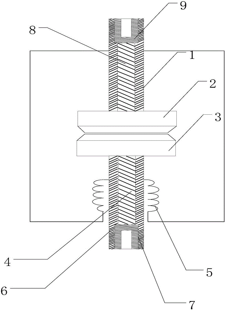
[0016] like figure 1 As shown, a conductive rod structure of a vacuum interrupter provided by the present invention includes a static conductive rod 1, a moving conductive rod 6, a static conductive rod core 8, a moving conductive rod core 4, a static contact 2, and a moving contact 3 , bellows 5, moving conductive rod joint 7 and static conductive rod joint 9.

[0017] Among them, one end of the moving conductive rod 6 is equipped with a moving contact 3, and the other end of the moving conductive rod 6 is equipped with a bellows 5 and a moving conductive rod joint 7; one end of the static conductive rod 1 is equipped with a static contact 2, and the static conductive rod The other end of 1 is equipped w...


PUM


Abstract

A conductive rod structure for a vacuum interrupter belongs to the technical field of electrical switches. The dynamic and static conductive rods are equipped with dynamic and static conductive rod cores. The dynamic and static conductive rod cores are located at the center of the dynamic and static conductive rods. One end of the dynamic and static conductive rods is connected with a dynamic and static contact. The moving contact is in flush contact, and the lower end of the steel core of the static conductive rod is in flush contact with the static contact. The mechanism of the invention is simple, by assembling the structure of the dynamic and static conductive rod cores in the center of the dynamic and static conductive rods, the mechanical strength of the dynamic conductive rod is effectively improved, and the conductive rod structure of the fast mechanical switch is prevented under the same extrusion stress Roughly deformed due to mechanical impact, good mechanical properties and low processing cost. The density of the core material of the dynamic and static conductive rods is lower than that of copper, which reduces the mass of the dynamic conductive rod, thereby reducing the closing bounce and ensuring electrical performance.

Description

technical field [0001] The invention belongs to the technical field of electric switches, and relates to a conductive rod structure of a vacuum interrupter. Background technique [0002] Vacuum interrupter, also known as vacuum switch tube, is the core component of medium and high voltage power switch. Its main function is to quickly extinguish the arc and suppress the current after the medium and high voltage circuit cuts off the power supply through the excellent insulation performance of the vacuum inside the tube, so as to avoid nuclear accidents. The occurrence of accidents is mainly used in power transmission and distribution control systems of electric power, and also in power distribution control systems of metallurgy, mining, petroleum, chemical industry, road broadcasting, communication, and industrial high-frequency heating. It has the characteristics of energy saving, material saving, fire prevention, explosion protection, small size, long life, low maintenance c...

Claims


Application Information

Patent Timeline
Patent Type & Authority Applications(China)
IPC IPC(8): H01H33/664
CPCH01H33/664
Inventor 梁伟朋
Owner DALIAN UNIV OF TECH
Why Eureka
Try Eureka