Real-time voltage detection and protection circuit for PFC boost converters

a protection circuit and converter technology, applied in the field of real-time voltage detection and protection circuits of pfc boost converters, can solve the problems of excessive downtime of the pfc boost circuit, unacceptable load on the line supply transformer, and abnormal demands on the line supply, so as to reduce the down time of the converter, the effect of avoiding unnecessary down tim

Inactive Publication Date: 2005-12-08
ASTEC INT LTD
View PDF17 Cites 56 Cited by
  • Summary
  • Abstract
  • Description
  • Claims
  • Application Information

AI Technical Summary

Benefits of technology

[0010] The present invention overcomes the drawbacks of known circuits by providing a circuit having a real-time fast comparison circuit for comparing the input rectified AC instantaneous voltage against the output voltage in a PFC boost-type converter. The boost function of a PFC controller in the boost converter is enabled or disabled as a function of the output of the comparison circuit whose inputs are unfiltered representations of the input sine wave voltage and output DC voltage of the PFC boost converter. The circuit according a preferred embodiment includes a real-time input voltage detection circuit and complementary protection circuit for enabling protection of the converter against input glitches and output surges, and enabling near-immediate recovery of boost operation after momentary failures so as to avoid unnecessary down time.
[0011] Broadly stated, the present invention provides a circuit for providing protection for a boost converter during power disturbance conditions, said boost converter having a switch, an inductor, a diode, two input terminals to which an input DC voltage is coupled and two output terminals where the output DC power is provided, a pulse width modulated PFC controller for providing a boost function for controlling the duty cycle of said switch for controlling said output voltage, comprising: a detection circuit for detecting said input voltage instantaneously such that a real time sample of said input voltage is detected; a comparator circuit for comparing said real time input voltage sample and said output voltage; wherein the boost function of the PFC circuit is enabled or disabled as a function of the output of said comparator circuit so as to disable said boost function during power line disturbances and to reenable said boost function so as to reduce the down time for said converter.

Problems solved by technology

Power supplies for generating a predetermined voltage / current for a given application can make abnormal demands on the line supply caused by the harmonic content of the current drawn from the line.
In particular, a high third harmonic content can give a large neutral current which can place unacceptable loads on the line supply transformer.
The result is excessive downtime for the PFC boost circuit.
In the case of short glitches appearing on the input power line, the protection circuit for converter 10 fails to adequately protect the PFC boost converter since the response time of the filtered circuit is too slow to provide the required protection.
In the case of a sudden high voltage surge on the input voltage line, the converter 10 in FIG. 1 has the drawback that it causes the PFC to latch in order to avoid damage to the power supply unit.
Thus, in the case of high voltage surges at the input, the prior art circuit shuts down the operation of the unit rather than providing a way in which circuit operation can be maintained during such conditions.
Although PFC boost converters using PFC controllers such as the L4981 are fast enough to enable boost during fractions of the input voltage half-sine wave, no prior art circuit has utilized this feature to speed up boost response.

Method used


Image

  • Real-time voltage detection and protection circuit for PFC boost converters
  • Real-time voltage detection and protection circuit for PFC boost converters
  • Real-time voltage detection and protection circuit for PFC boost converters

Examples


Embodiment Construction

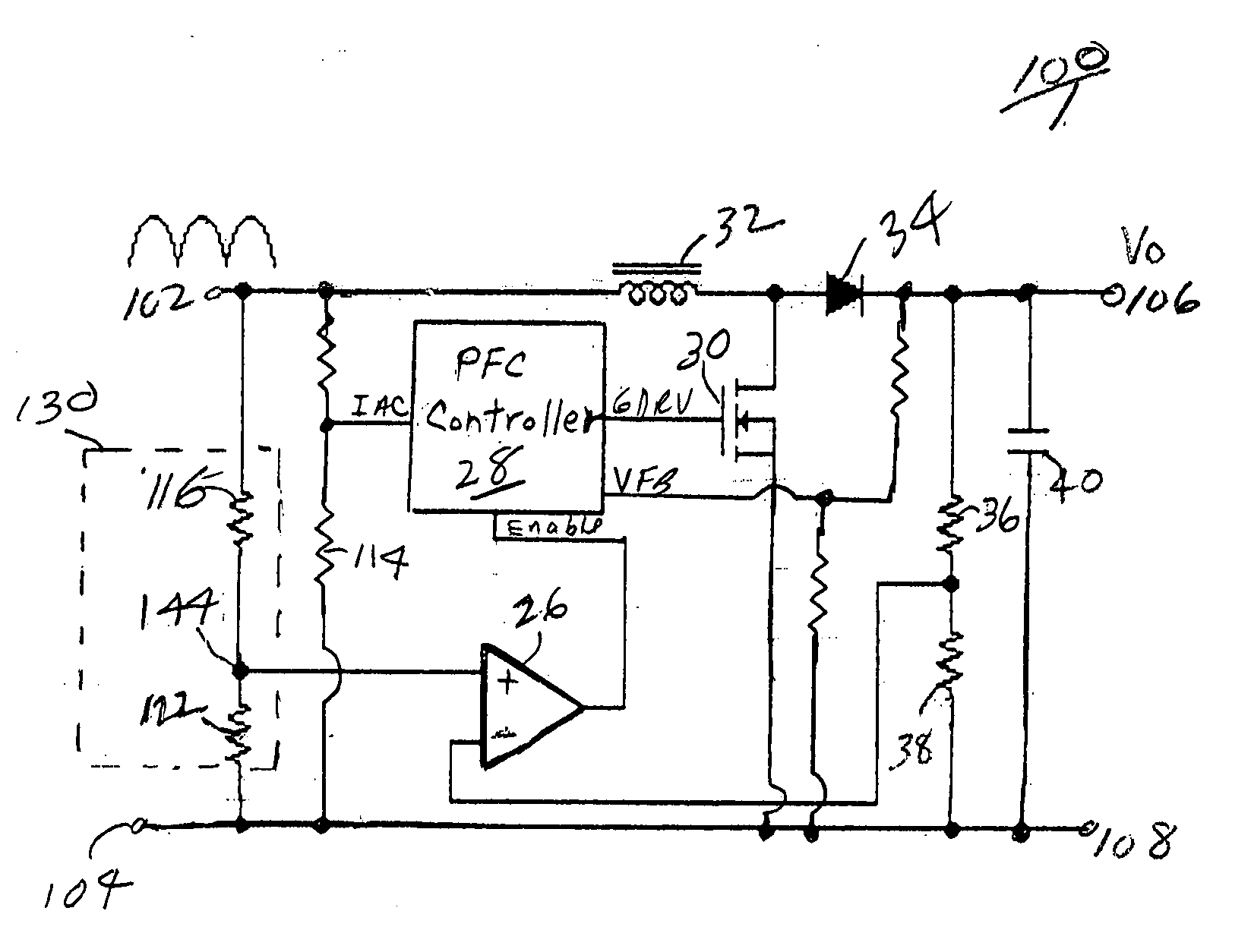
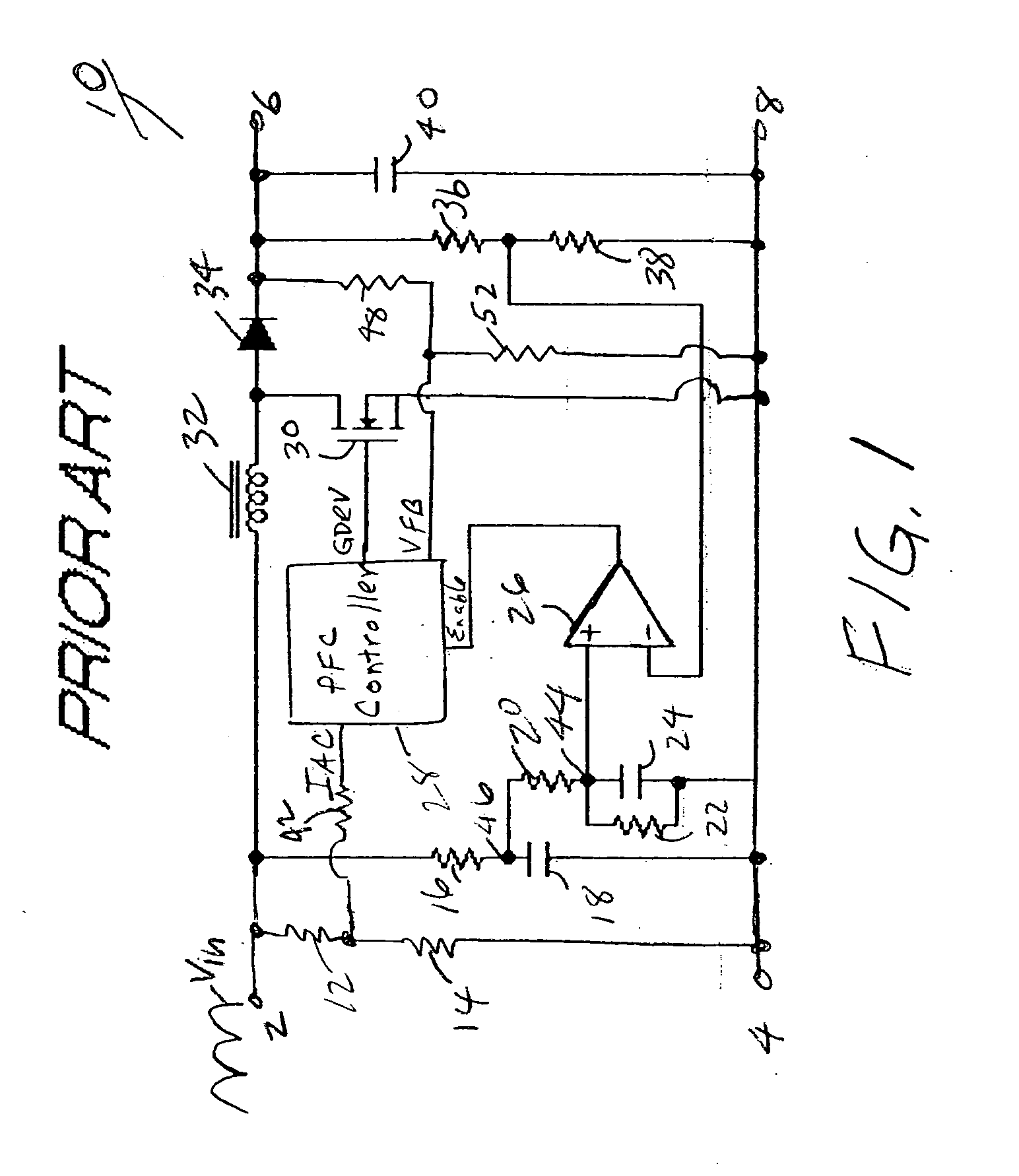
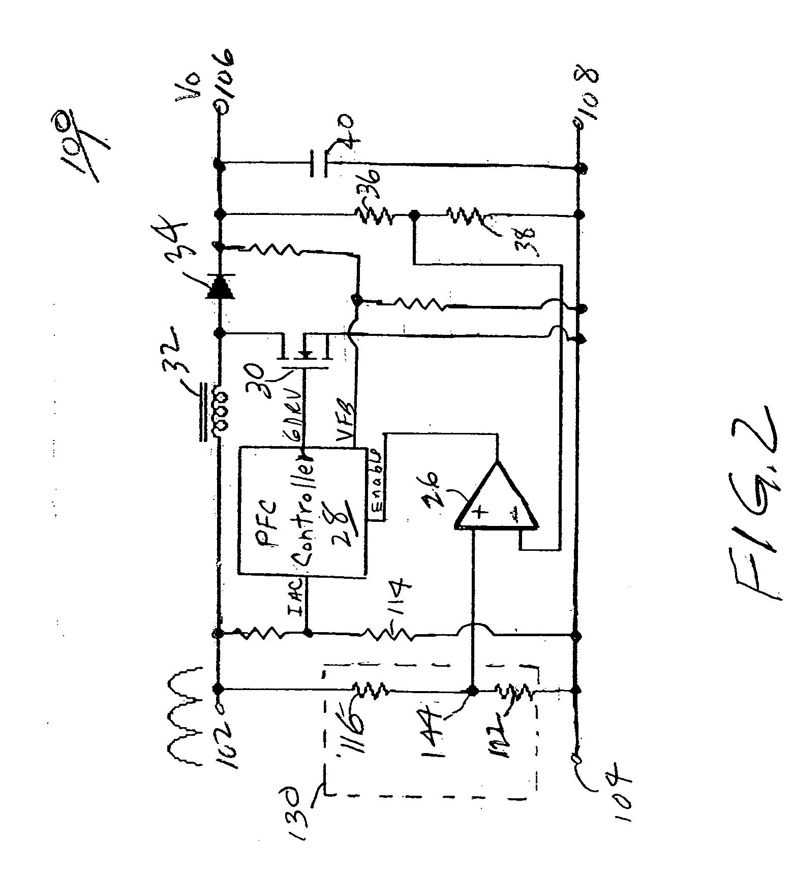
[0021] A convention boost converter as described above uses a switching technique to boost a rectified input line voltage to a regulated DC output voltage for delivery to a load. For power factor correction, the conventional boost converter includes a PFC controller for modifying the current waveform to reduce the harmonics and thus enable the current waveform to more closely define a sinusoidal waveform that is in phase with the line voltage. The prior art boost converter shown in FIG. 1 includes an inhibit circuit to turn off the boost function under certain conditions. The prior art circuit uses filter capacitors to provide a filtered, averaged, non-real-time voltage representation of the rectified input voltage to compare to the output voltage to determine if the boost function should be inhibited, i.e. disabled. Among other drawbacks, the inclusion of filter capacitors in the circuit of FIG. 1 introduce a substantial delay before enabling the boost function after the rectified ...


PUM


Abstract

A circuit for protection of the operation of power factor correction (PFC) converters from conditions such as input voltage surges that can otherwise cause failure, and to prevent unnecessary down time of the boost converter after a power failure or on startup. The circuit detects the real time rectified input voltage and provides real time comparison of the detected input voltage and the output voltage. The boost function of the PFC is controlled as a function of the output of the comparison circuit so as to quickly inhibit the boost function of the PFC controller thereby disabling boost and protecting the circuit from burning out. The circuit enables the PFC to starts and restart more quickly, even before the output voltage becomes stabilized, since boost is permitted as soon as the output voltage exceeds the real time sampled input voltage. By enabling boost during this period, the circuit eliminates the need to wait at least a few cycle times until the output voltage is higher than the peak of rectified input voltage. In a preferred embodiment, a complementary protection circuit having a voltage clamp is also provided to prevent unnecessary shutdown of the converter.

Description

FIELD OF INVENTION [0001] The present invention relates in general to power factor correction circuits, and more particularly, to a power factor correction circuit for a boost-type converter that controls the boost function for protection of the converter during selected failure conditions and faster recovery thereafter. BACKGROUND OF INVENTION [0002] Power supplies for generating a predetermined voltage / current for a given application can make abnormal demands on the line supply caused by the harmonic content of the current drawn from the line. In particular, a high third harmonic content can give a large neutral current which can place unacceptable loads on the line supply transformer. To compensate for this problem, power factor correction (PFC) circuits have been developed to reduce the harmonic content. A conventional AC to DC power converter typically includes a boost converter for power factor correction of the input bulk voltage generated from the AC input power source and a...

Claims


Application Information

Patent Timeline
Patent Type & Authority Applications(United States)
IPC IPC(8): G05F1/10H02M1/32H02M1/36
CPCH02M1/36H02M1/32Y02P80/10
Inventor LIU, CHI FAIMONCADA, JOSE AGERICO
Owner ASTEC INT LTD
Why Eureka
Try Eureka