Imaging apparatus

a technology of ic tags and images, applied in the field of ic tags, can solve the problem of inability to obtain the correspondence between the information read from the ic tag and the image of an articl

Inactive Publication Date: 2005-12-08
FUJIFILM CORP
View PDF2 Cites 15 Cited by
  • Summary
  • Abstract
  • Description
  • Claims
  • Application Information

AI Technical Summary

Benefits of technology

[0005] A method of managing an article by shooting it as a subject and using a shot image is effective. However, when an article with an IC tag attached to it is shot, it is necessary to manage information read from the IC tag together with an image recorded on the recording material. However, the technology of Japanese Patent Application Laid Open No. 2004-72146 only associates an image recorded on a recording material with the information such as the storage position of image data, etc. Thus, the correspondence between the information read from the IC tag and the image of an article cannot be obtained. The present invention has been developed to solve the above-mentioned problems and aims at providing an imaging apparatus capable of associating the information read from an IC tag attached to a subject with an image obtained by capturing the subject.

Problems solved by technology

Thus, the correspondence between the information read from the IC tag and the image of an article cannot be obtained.

Method used


Image

  • Imaging apparatus
  • Imaging apparatus
  • Imaging apparatus

Examples


first embodiment

[Outline of the Configuration]

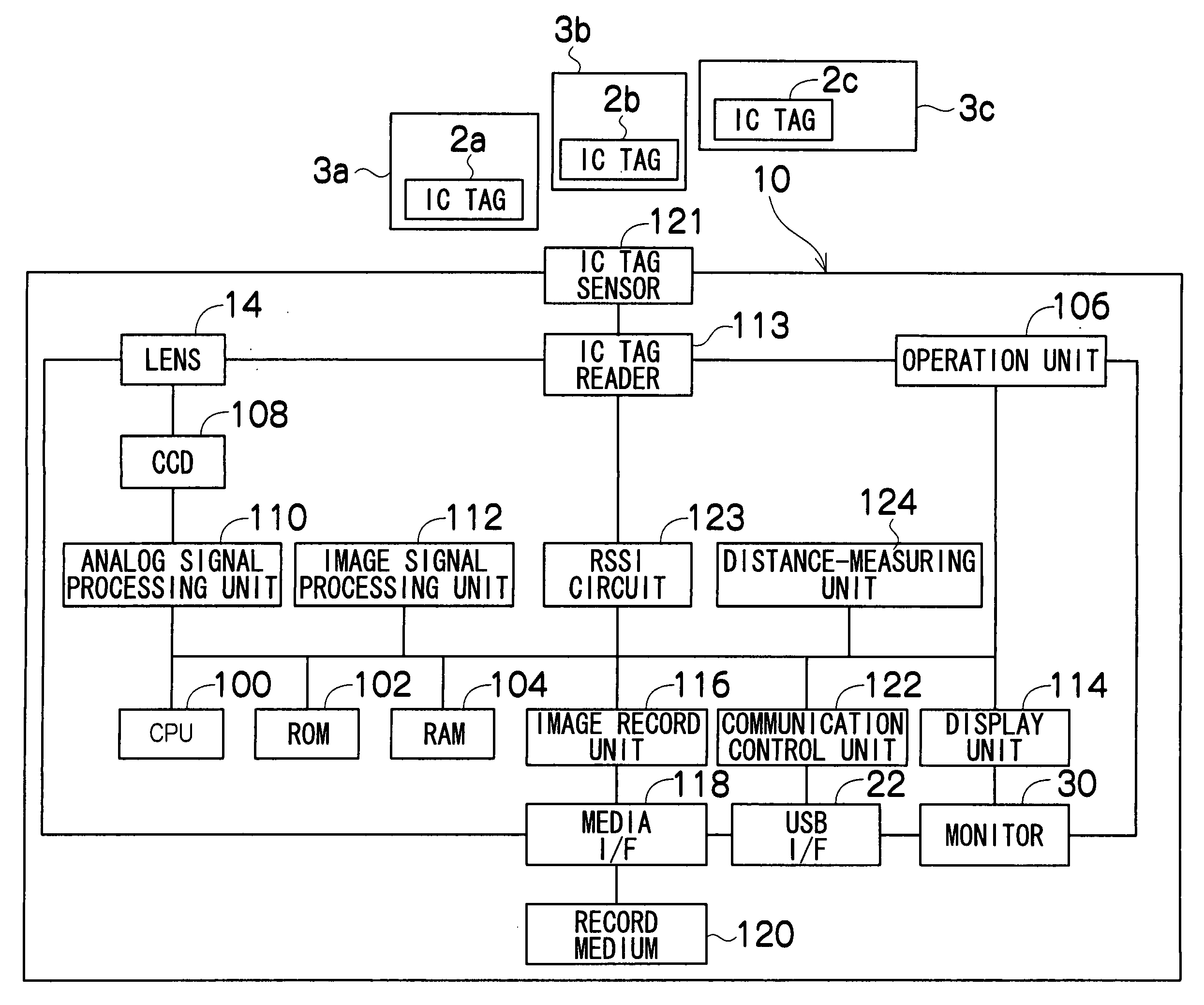
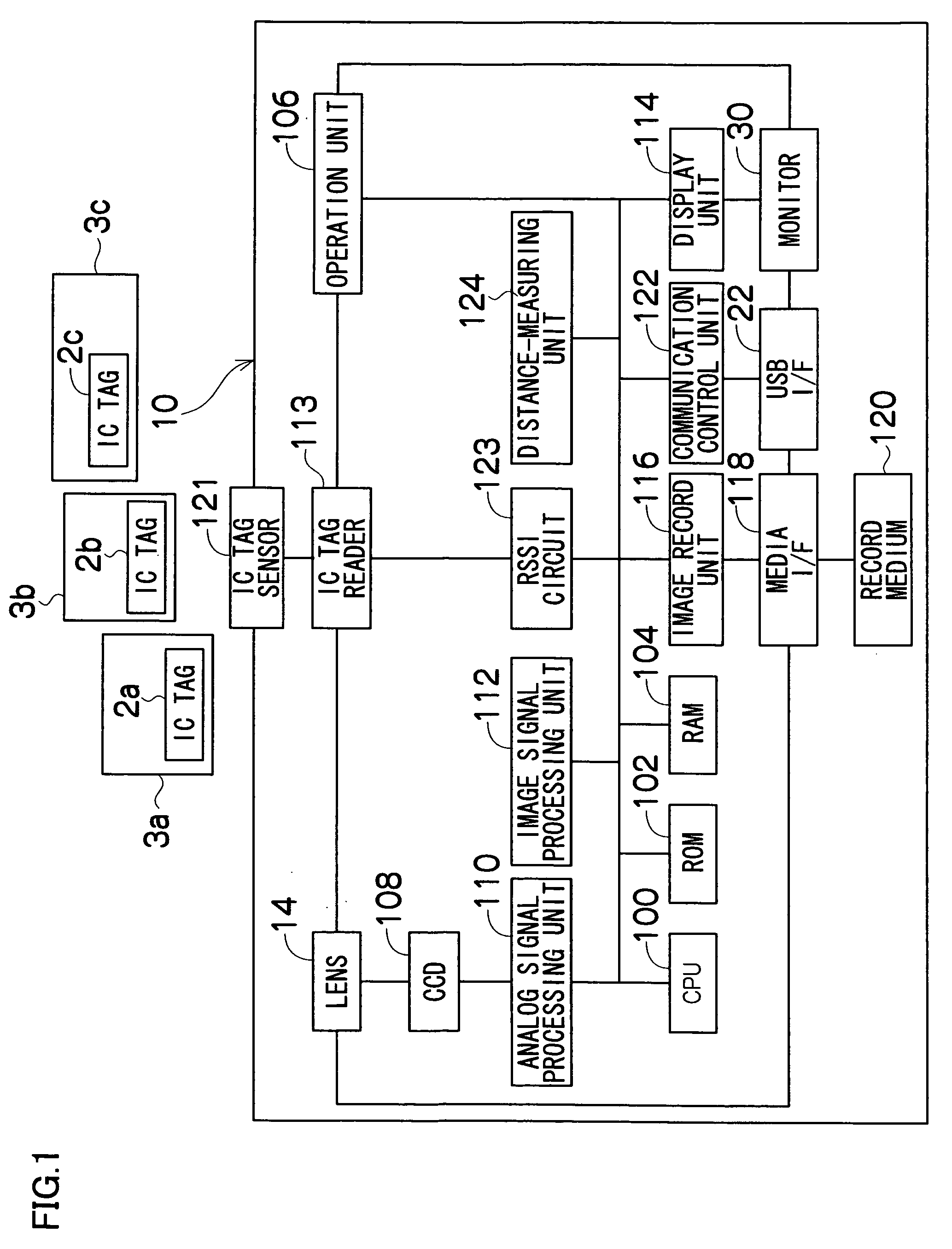
[0027]FIG. 1 is a block diagram showing an outline of the configuration of a digital camera 10 according to the preferred embodiments of the present invention. In FIG. 1, a CPU 100 is a control unit for centrally controlling each circuit of the present camera system, and comprises ROM 102, RAM 104, etc. The ROM 102 stores a program, various types of data, etc. required for control by the CPU 100. The RAM 104 is used as a work area in performing various arithmetic operations, etc. by the CPU 100. The ROM 102 is configured by flash ROM capable of erasing / writing data.

[0028] The CPU 100 controls the operation of a corresponding circuit based on an operation signal output from an operation unit 106 comprising a release button, a power source button, a strobe button, a macro button, a zoom lever, a display button, a BACK button, a mark button, a menu / OK button, a cross button, a mode switch, etc., performs lens drive control, shooting operation control, im...

second embodiment

[0048] The present invention can be applied to a silver salt camera not provided with an image pickup element such as a CCD 108. For example, as in the first embodiment, the silver salt camera can be provided with the IC tag sensor 121, the IC tag reader 113, the CPU 100, the ROM 102, the RAM 104, and the operation unit 106. While the fully pressed shutter button of the operation unit 106 stores an image on the silver salt film, the information in which the frame number of the image is associated with the IC tag information is stored in a magnetic film, a semiconductor storage device, etc., thereby associating the shot image through the frame number with the IC tag information read from the IC tag. The silver salt camera can be further provided with the RSSI circuit 123, thereby detecting the intensity of the received radio signal from the IC tag 2, and recording the detected intensity as associated with the frame number. Otherwise, the silver salt camera can be further provided wit...


PUM


Abstract

An imaging apparatus, comprising a receiving unit which receives a radio signal from an IC tag attached to a subject, a read unit which reads IC tag information recorded on an IC tag from each received radio signal, an image pickup unit which captures the subject and a first storage unit which stores IC tag information read from the IC tag and an image captured by the image pickup unit after associating the information with the image.

Description

BACKGROUND OF THE INVENTION [0001] 1. Field of the Invention [0002] The present invention relates to an imaging apparatus, and more specifically to an imaging apparatus capable of associating the information about an IC tag attached to a subject with a captured subject image. [0003] 2. Related Art [0004] Recently a very small device containing an integrated circuit with memory called an IC tag and an antenna for wireless communications has been developed. An IC tag is used in managing articles by attaching it as a tag to various articles. For example, according to Japanese Patent Application Laid Open No. 2004-72146, an image record area is provided around the center of an instant film inserted to a digital still camera (DSC) having a built-in printer, an enclosing unit which encloses a development and fixing agents is provided at one end of it, and an agent receiver is provided at the other end of it. The printer included in the DSC records an image in the image recording area, and...

Claims


Application Information

Patent Timeline
Patent Type & Authority Applications(United States)
IPC IPC(8): H04N1/00H04N5/225H04N5/232
CPCH04N1/00127H04N1/00342H04N5/23212H04N2201/3274H04N2201/0055H04N2201/0084H04N2201/3225H04N2101/00H04N23/673H04N23/675H04N23/635
Inventor YAMAGUCHI, YOSHIHIRO
Owner FUJIFILM CORP
Why Eureka
Try Eureka