Disk array device and battery output control method for disk array device

a technology of battery output control and disk array device, which is applied in the direction of fault response, recording signal processing, instruments, etc., can solve the problems of low reliability of technique and no great consideration

Inactive Publication Date: 2005-12-08
GOOGLE LLC
View PDF14 Cites 36 Cited by
  • Summary
  • Abstract
  • Description
  • Claims
  • Application Information

AI Technical Summary

Problems solved by technology

However, no great consideration is given to the battery output control method or the like, so that there is a possibility of problems.
Thus, this technique suffers from low reliability.

Method used


Image

  • Disk array device and battery output control method for disk array device
  • Disk array device and battery output control method for disk array device
  • Disk array device and battery output control method for disk array device

Examples


first embodiment

1. First Embodiment

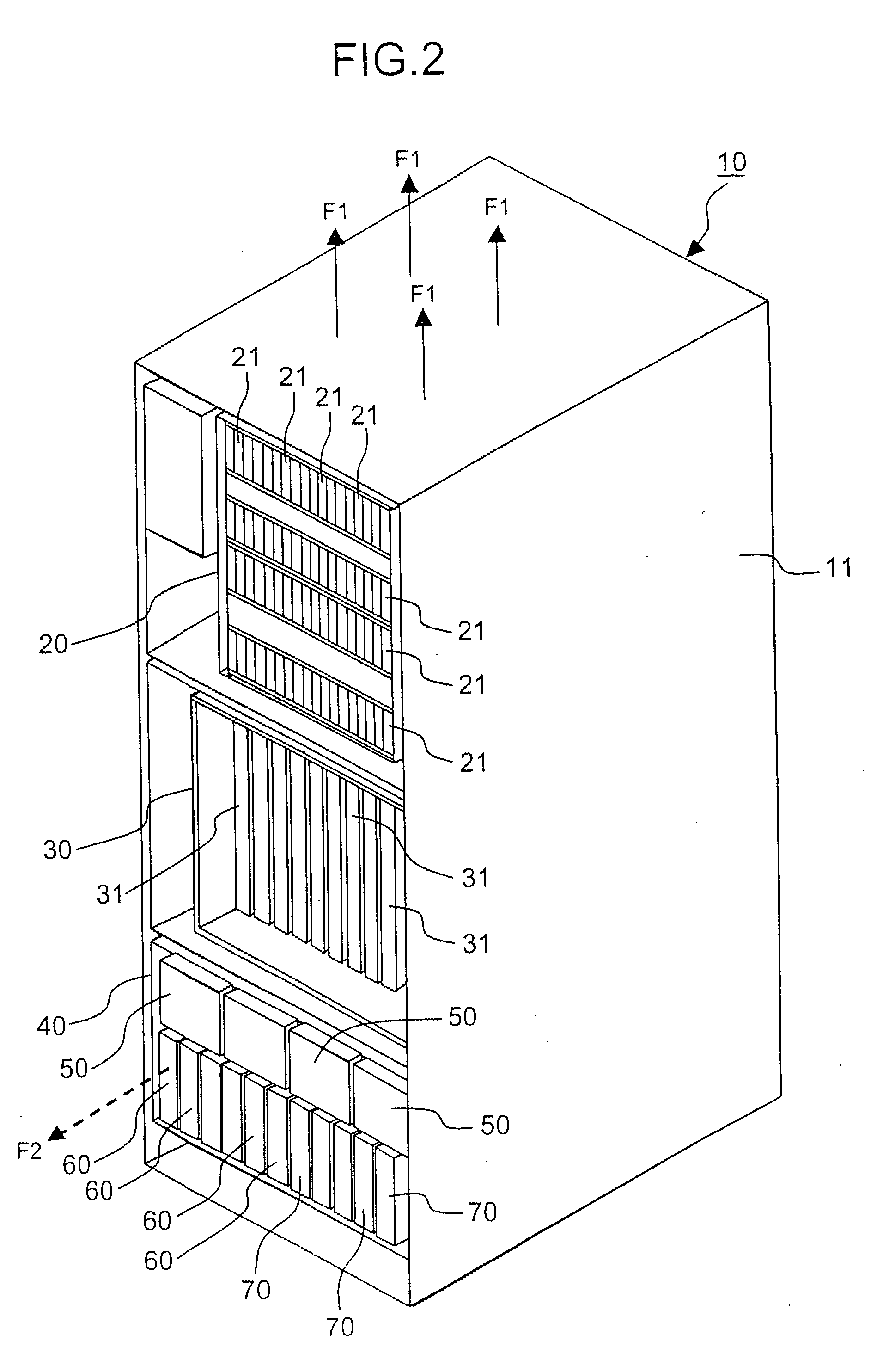
[0060]FIG. 2 is an external view of the disk array device 10. The disk array device 10 can be constructed so that this disk array device comprises a housing 11, and a memory part 20, controller 30 and power supply 40 that are disposed inside this housing 11.

[0061] The memory part 20 can be disposed in the upper part of the housing 11. The memory part 20 is constructed from numerous disk drives 21 that are detachably mounted in the housing 11. For example, the disk drives 21 can be constructed as hard disk drives; however, these disk drives 21 can also be constructed as semiconductor memory devices, optical disk drives or the like.

[0062] The controller 30 can be disposed in the housing 11 so that this controller is positioned beneath the memory part 20. For example, various types of control circuit boards 31 that function as CHAs and DKAs are detachably mounted in the controller 30.

[0063] The power supply 40 can be disposed in the lowermost part of the housing 1...

second embodiment

2. Second Embodiment

[0133] A second embodiment of the present invention will be described with reference to FIGS. 10 and 11. The characterizing feature of this embodiment is that an output controller 670 that is used to control the operation of the discharge circuit 650A is provided, and the system is devised so that the discharge circuit 650A is operated with the temperature of the battery cells being taken into account. Furthermore, the embodiments described below, including this embodiment, correspond to modifications of the first embodiment.

[0134]FIG. 10 is a circuit diagram that focuses on the power supply circuit of the disk array device 10. Because of space limitations, the symbol “51” of the power supply common bus is omitted; however, the two thick lines at the left end of the figure express this power supply common bus 51.

[0135] The battery boxes 60A of this embodiment have the same construction as in the first embodiment; however, this embodiment differs from the first ...

third embodiment

3. Third Embodiment

[0150] A third embodiment [of the present invention] will be described with reference to FIGS. 12 through 15. One characterizing feature of the present embodiment is as follows: namely, in the instantaneous power outage holding period in which an instantaneous large power is required, variation in the output among the battery boxes 80 is positively utilized, while in the destage control period and memory backup period in which a stable long-term power supply is required, control is performed so that the variation in the output among the battery boxes 80 is suppressed.

[0151]FIG. 12 is an external view of the disk array device 10A of this embodiment. Like the disk array device 10 of the first embodiment, this disk array device 10A comprises a memory part 20, controller 30 and power supply 40A. However, the power supply 40A of this disk array device 10A comprises a plurality of separate battery boxes 80 that differ from the battery boxes 60 of the abovementioned emb...


PUM

PropertyMeasurementUnit
currentaaaaaaaaaa
output currentaaaaaaaaaa
currentaaaaaaaaaa

Abstract

The disk array device supplies appropriate power to various parts in accordance with the operating mode in cases where the output of the main power supply drops. The disk array device adjusts the power from a commercial power source 6 with an AC/DC power supply 5, and supplies this power to a power supply common bus 7. A disk drive group 1 and a control circuit board group 2 constituting electrical loads are respectively connected to the power supply common bus 7. When the supply of power from the main power supply stops, the capacitor box 3 supplies a relatively large current for a short time only, in order to retain data during an instantaneous power outage. Then, the battery boxes 4 supply power to the power supply common bus 7 for a relatively long period of time, in order to perform destage control and memory backup. The battery boxes 4 perform balancing control of the output current in order to suppress variation in the output current value among the battery boxes 4.

Description

CROSS-REFERENCE TO RELATED APPLICATIONS [0001] This application relates to and claims priority from Japanese Patent Application No. 2004-164007 filed on Jun. 2, 2004, the entire disclosure of which is incorporated herein by reference. BACKGROUND OF THE INVENTION [0002] The present invention relates to a disk array device and a battery output control method for this disk array device. [0003] For example, a disk array device is constructed by disposing memory devices such as hard disk drives, semiconductor memory devices or the like in the form of an array. A disk array device provides logical memory regions based on an RAID (redundant array of independent inexpensive disks). These logical memory regions are also called “logical volumes” (LU: logical units). [0004] Host computers access the logical volumes, and perform the reading and writing (I / O) of data. The exchange of data between the host computers and logical volumes is accomplished via a memory. [0005] Such a disk array device...

Claims


Application Information

Patent Timeline
Patent Type & Authority Applications(United States)
IPC IPC(8): G06F1/26G06F3/06G11B33/12G06F1/20G11B5/09G06F1/00G06F11/14G06F1/30G06F1/32
CPCG06F1/263G06F1/305G06F1/3221Y02D10/154G06F11/1441G06F2003/0692G11B33/126G06F3/0601G06F3/0673Y02D10/00
Inventor HAYASHI, KATSUNORI
Owner GOOGLE LLC
Why Eureka
Try Eureka