Radio module

a radio module and module technology, applied in the field of radio modules, can solve the problems of reducing the size of the reception buffer, hindering the performance of a required transmission process, and wasting memory resources,

Inactive Publication Date: 2005-12-08
PANASONIC CORP
View PDF5 Cites 36 Cited by
  • Summary
  • Abstract
  • Description
  • Claims
  • Application Information

AI Technical Summary

Benefits of technology

[0044] This arrangement can easily cope with an increase in the contents types that a user can select, or the addition or changing of a contents processor, such as an AV apparatus, that is to be connected to a wireless communication unit that serves as a transmission source.
[0045] According to the invention, since the transmission buffer area and the reception buffer area for the buffer queue are changed in accordance with the contents type, the sizes of the buffers required for the transmission process and the reception process can always be optimized, and the memory resources can be utilized effectively.
[0046] Furthermore, since the wireless communication unit constantly obtains the sizes of the buffers required for the transmission process and the reception process, it is possible to prevent the occurrence of a phenomenon whereby, although the size of the reception buffer is adequate, the size of the transmission buffer is reduced, thereby hindering the performance of a required transmission process, and also of a phenomenon whereby, although the size of the transmission buffer is adequate, the size of the reception buffer is reduced, and the performance of a required reception process is hindered.

Problems solved by technology

However, a wireless communication function has also begun to be mounted in electric household appliance, such as AV apparatuses, to perform video transmission, and high quality wireless transmission is also required in environments wherein abundant memory resources, like those provided by PCs, are not available.

Method used


Image

  • Radio module
  • Radio module
  • Radio module

Examples


first embodiment

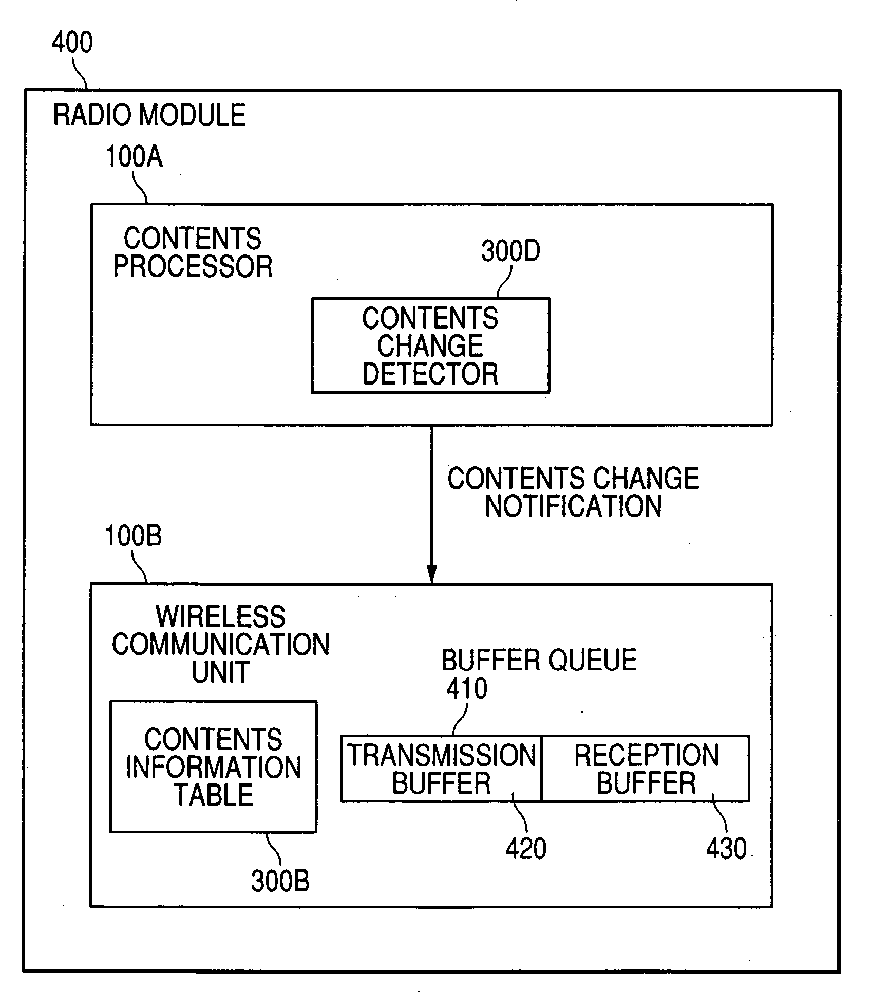
[0061]FIG. 3 is a schematic block diagram showing the configuration of a radio module 400 according to a first embodiment of the present invention. The radio module 400 for this embodiment comprises: a wireless communication unit 100B, for performing wireless communication for the contents; and a contents processor 100A, for processing the contents that are to be transmitted or that are received by the radio communication unit 100B.

[0062] Included in the contents processor 100A is a contents change detector 300D. When the contents are changed, the contents change detector 300D transmits to the wireless communication unit 100B a contents identifier corresponding to the contents that are newly to be processed by the wireless communication unit 100B.

[0063] The wireless communication unit 100B includes a contents information table 300B, in which information concerning the contents is stored. The wireless communication unit 100B examines the contents information table 300B, and based o...

second embodiment

[0079] The contents are not always transmitted or received at a specific, constant rate. The rate at which the contents are stored in the contents information table 300B in FIG. 4 is the average rate for the contents, and were the rate to be locally increased, this would cause a buffer overflow.

[0080] Therefore, as is shown in FIG. 8, an entry for use history is added to the contents information table 300B. The use history then corresponds to the maximum sizes of buffers actually used, in the past, for transmission and reception. Since, however, the buffer use history information for the individual contents is retained, the maximum sizes of buffers actually used in the past can be obtained. In this embodiment, basically, instead of the sizes of buffers being calculated based on the average rate, buffers having sizes based on the use history are allocated for the transmission buffer 420 and the reception buffer 430.

[0081] However, when the total size of a buffer nears the limit, th...

third embodiment

[0084] For wireless data communication, the error state may constantly be changed due to the installation location or the interference provided by an obstacle or another wireless device. Because of this, the optimal distribution of the transmission buffer 420 and the reception buffer 430 may not be obtainable even when these buffers are appropriately distributed in accordance with the communication rate.

[0085] To cope with this case, at a specific interval, a transmission terminal collects statistics on for the frequency of transmissions and the frequency of errors, calculates the error rate based on the obtained statistic data, and changes the size of the buffer in accordance with the error rate. In this manner, the optimal size of the buffer can always be distributed.

[0086] In FIG. 10, the required size of the buffer for each error rate is additionally entered as an error correction value to the contents information table 300B. In this embodiment, the size of the buffer is rearr...


PUM


Abstract

The objective of the invention is the constant optimization of the sizes of buffers required for a transmission process and a reception process, and the effective use of memory resources. A contents processor includes a contents change detector. When the contents are changed, the contents change detector transmits to a wireless communication unit a contents identifier corresponding to contents that are to be newly processed by the wireless communication unit. The wireless communication unit includes a contents information table in which information concerning the contents is stored. The wireless communication unit examines the contents information table, obtains the sizes of buffers required for a transmission process and a reception process, based on the contents identifier transmitted by the contents processor, and redistributes the transmission buffer and the reception buffer for a buffer queue.

Description

BACKGROUND OF THE INVENTION [0001] 1. Field of the Invention [0002] The present invention relates to optimal control provided for a transmission buffer and a reception buffer during wireless data communication. [0003] 2. Description of the Related Art [0004] A market, centered around PCs, has been developed for wireless communication systems, and the use of wireless communication systems has spread. Wireless communication systems can be constituted by employing the abundant memory resources available of a PC, without much having to take into account limitations imposed by the sizes of memories used for wireless communication. [0005] However, a wireless communication function has also begun to be mounted in electric household appliance, such as AV apparatuses, to perform video transmission, and high quality wireless transmission is also required in environments wherein abundant memory resources, like those provided by PCs, are not available. Therefore, optimal control of buffer sizes...

Claims


Application Information

Patent Timeline
Patent Type & Authority Applications(United States)
IPC IPC(8): H04B7/00H04B7/26H04L13/08H04L49/901H04M1/72439H04W4/00H04W88/02
CPCH04M1/72555H04N21/23406H04N21/6338H04N21/64738H04M1/72439
Inventor MIKAMI, TAROYOSHIDA, TAKESHIOGAWA, SUGURU
Owner PANASONIC CORP
Why Eureka
Try Eureka