Optical fiber coupling device, wavelength shifter, pressure sensor, acceleration sensor, and optical device

a technology of optical fiber coupling and wavelength shifter, which is applied in the direction of acceleration measurement using interia forces, nanotechnology, instruments, etc., can solve the problem of inability to vary the wavelength, and achieve the effect of precise wavelength selection

Inactive Publication Date: 2005-12-08
HAMAMATSU PHOTONICS KK
View PDF19 Cites 4 Cited by
  • Summary
  • Abstract
  • Description
  • Claims
  • Application Information

AI Technical Summary

Benefits of technology

[0025] In this case, since the two photonic crystals having different photonic band gaps differ

Problems solved by technology

However, with an optical fiber coupling device using

Method used


Image

  • Optical fiber coupling device, wavelength shifter, pressure sensor, acceleration sensor, and optical device
  • Optical fiber coupling device, wavelength shifter, pressure sensor, acceleration sensor, and optical device
  • Optical fiber coupling device, wavelength shifter, pressure sensor, acceleration sensor, and optical device

Examples


Embodiment Construction

[0034] Optical devices of embodiments of this invention shall now be described. The same elements or elements having the same functions shall be provided with the same symbols and redundant explanations shall be omitted.

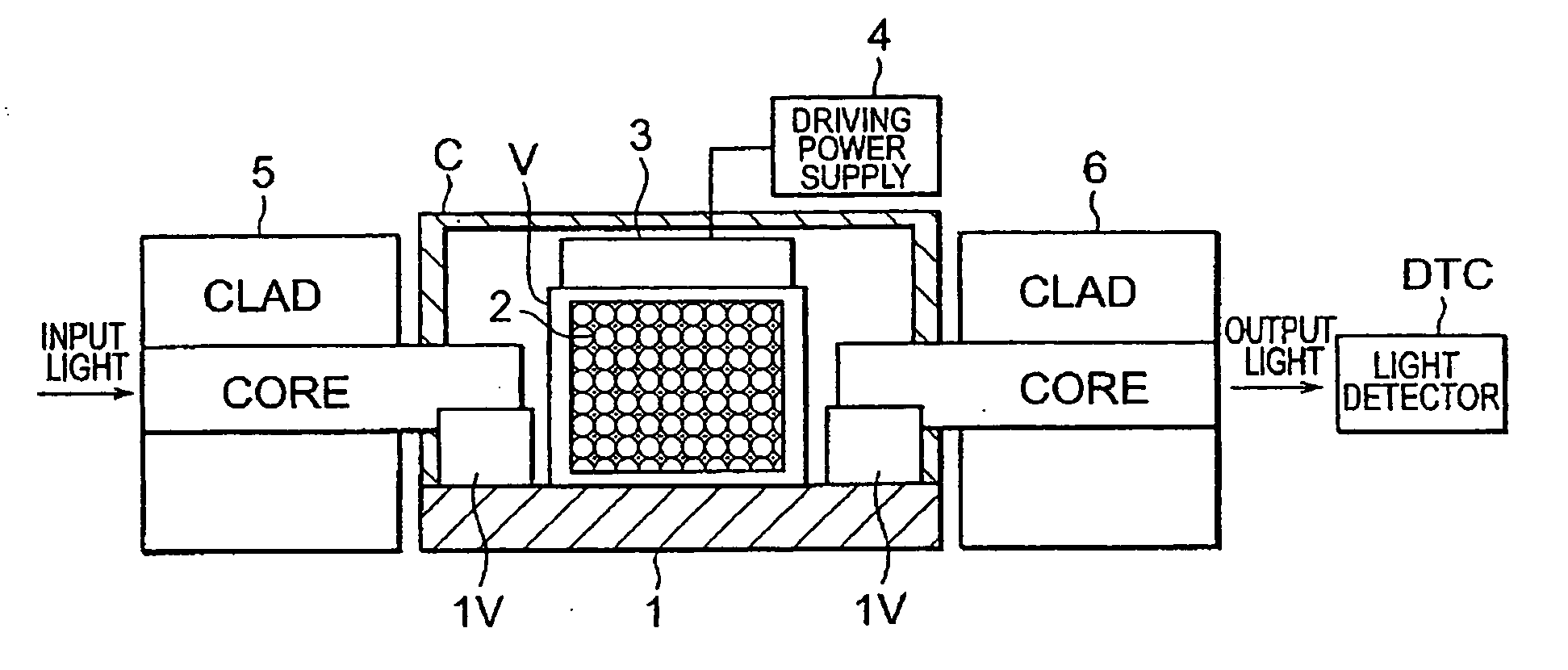
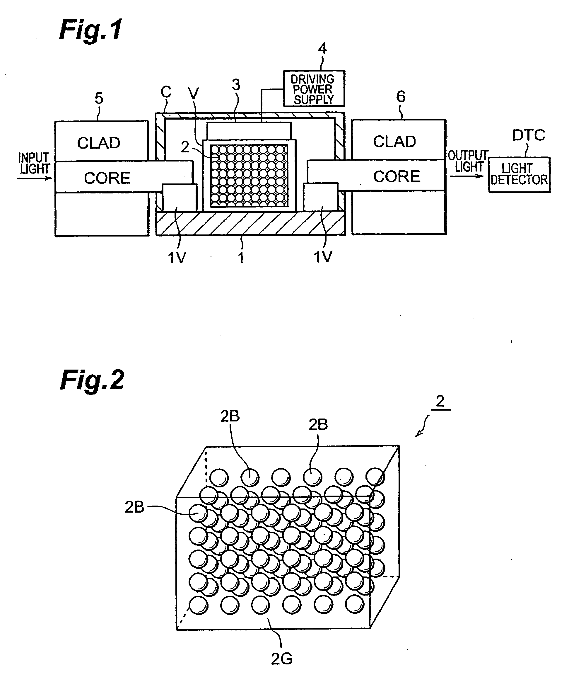
[0035]FIG. 1 is an explanatory diagram of an optical device of an embodiment that is an optical fiber coupling device. This optical fiber coupling device outputs output light that has been selected to be of a desired wavelength band among the wavelength band of input light. Each of the optical fibers comprises a core and a clad. A photonic crystal 2 is set on a base 1, and this photonic crystal 2 is urged by a piezoelectric element (external force application means) 3, which applies a pressure to photonic crystal 2 or reduces a pressure applied to photonic crystal 2.

[0036] Photonic crystal 2 deforms in a precise manner in accordance with the application of an external force and is a substance with which the photonic band gap changes in accordance with the deformati...


PUM


Abstract

A fiber coupling device comprises fixing parts 1V, to which the respective ends of two optical fibers 5 and 6 are fixed, photonic crystal 2, disposed inside the light path of light that propagates across the abovementioned ends, and external force application means 3, which applies an external force to photonic crystal 2. When an external force is applied by external force application means 3 to photonic crystal 2 while light is being propagated inside one optical fiber 5, the photonic band gap of photonic crystal 2 changes and light of a wavelength that is in accordance with this photonic band gap is output from the other optical fiber 5.

Description

TECHNICAL FIELD [0001] This invention concerns an optical fiber coupling device, a wavelength shifter, a pressure sensor, an acceleration sensor, and an optical device. BACKGROUND ART [0002] Optical fiber coupling devices that use optical fibers have been known since priorly, and such devices couple light, transmitted from one optical fiber, to another optical fiber. DISCLOSURE OF THE INVENTION [0003] However, with an optical fiber coupling device using optical fibers, the wavelength could not be varied. An object of this invention is to provide an optical fiber coupling device and a wavelength shifter with which the wavelength can be varied and to provide a pressure sensor and an acceleration sensor that use such optical devices. [0004] This invention's optical fiber coupling device comprises: a fixing part, to which the respective ends of two optical fibers are fixed; a photonic crystal, disposed in the light path of light that propagates between the abovementioned ends; and an ex...

Claims


Application Information

Patent Timeline
IPC IPC(8): G01L1/24G01L11/02G01P15/03G01P15/093G02B6/12G02B6/122G02B6/26G02B6/34G02B6/38G02B26/00
CPCB82Y20/00G01L1/24G01L11/02G01P15/093G02B6/1225G02B6/264G02B6/3845
Inventor TAKIGUCHI, YOSHIHIROITOH, KENSAKUYAMANAKA, JUNPEITAKASAKA, MASAOMI
Owner HAMAMATSU PHOTONICS KK
Why Eureka
Try Eureka