
Compressor blade with reduced aerodynamic blade excitation

Inactive Publication Date: 2005-12-08
ROLLS ROYCE DEUT LTD & CO KG
View PDF18 Cites 43 Cited by
  • Summary
  • Abstract
  • Description
  • Claims
  • Application Information

AI Technical Summary

Benefits of technology

[0005] A broad aspect of this invention is to provide a design of compressor blades such that, independently of the already suggested fixation of the flow transition point by applying a surface roughness to the suction side, oscillation of the compression shocks (suction side) and their vibration-augmenting coupling to the natural vibrations of the blade is avoided or reduced, in order to avoid damage to the compressor disks and blades occurring under certain operating conditions.
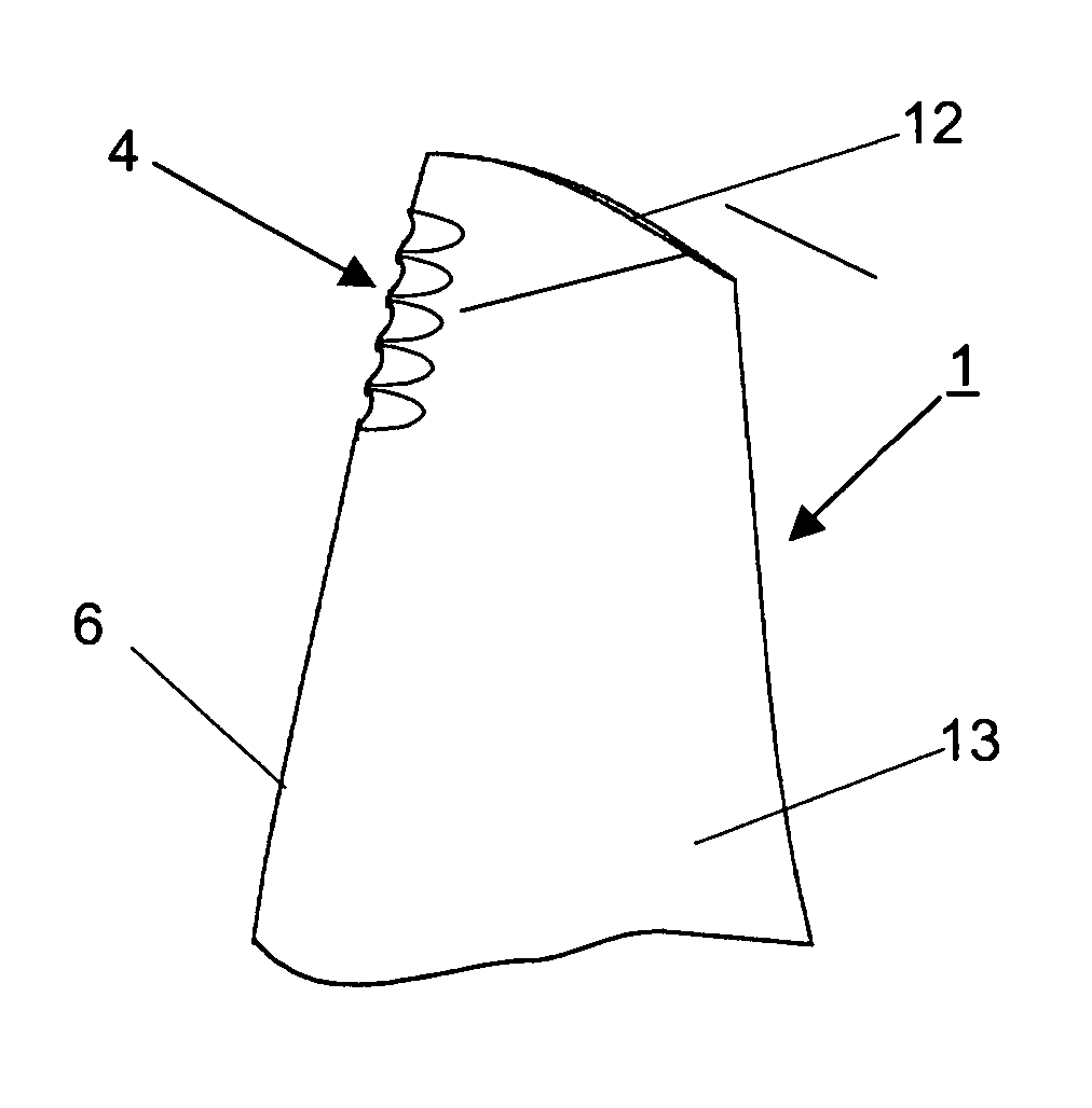
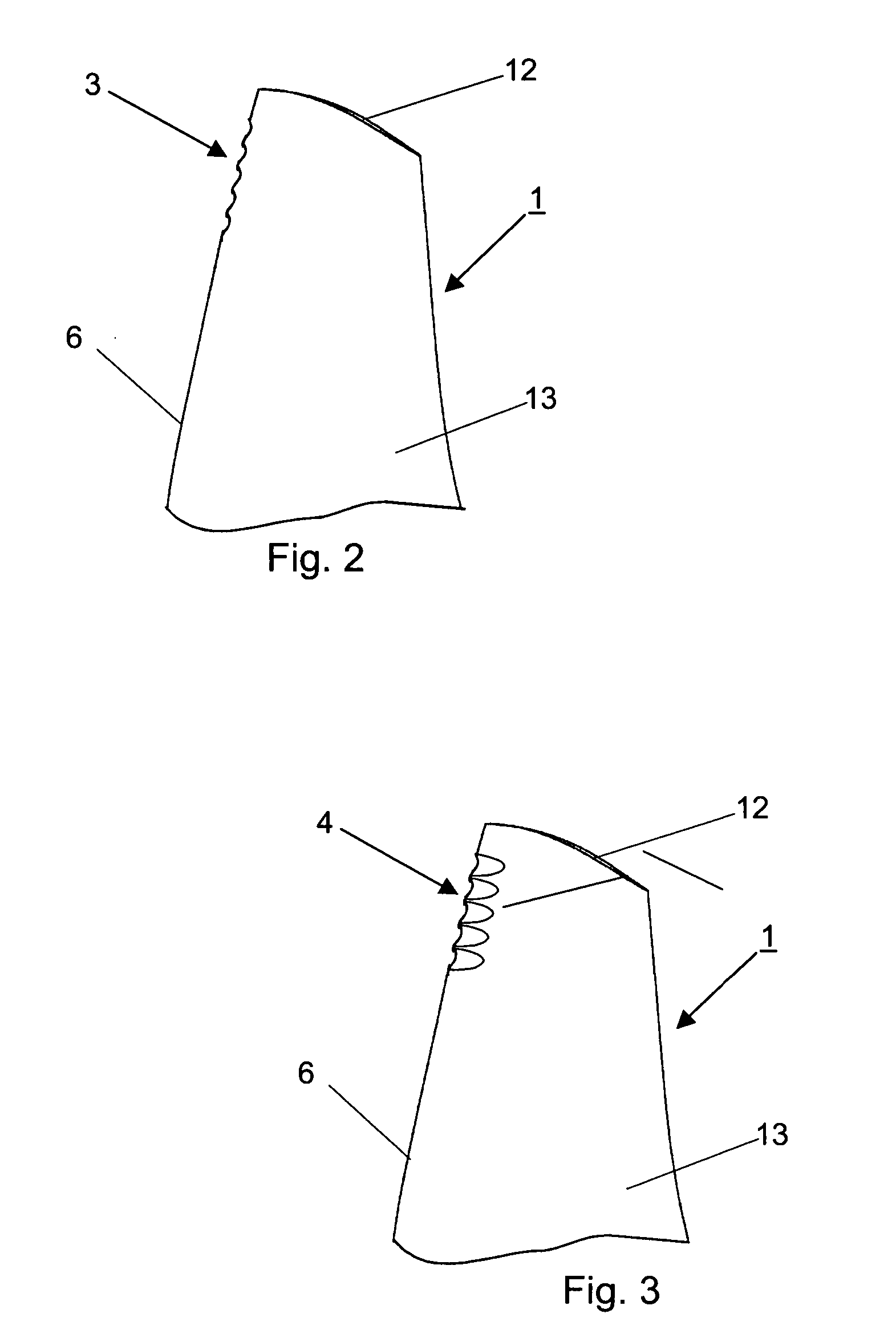
[0008] To achieve the above effects, the leading edge can, in the upper, natural-vibration critical area, also have a serrated structure, pocket-type depressions or a recessed area acting as sweep-back. Additionally, other designs of the blade leading edge are possible to ensure attachment of the leading edge shock wave to the blade leading edge and avoid acceleration and re-lamination of the turbulent boundary layer flow along the subsequent, suction-side curvature. Local disturbances in the boundary layer are produced which support the flow transition fixation.

Problems solved by technology

Compressor blades with a large chord length used on certain types of aircraft-engine compressors are loaded to such an extent under certain operating conditions that damage to or life reduction of the compressor blade and the compressor disk may occur.

Method used


Image

  • Compressor blade with reduced aerodynamic blade excitation
  • Compressor blade with reduced aerodynamic blade excitation
  • Compressor blade with reduced aerodynamic blade excitation

Examples


Embodiment Construction

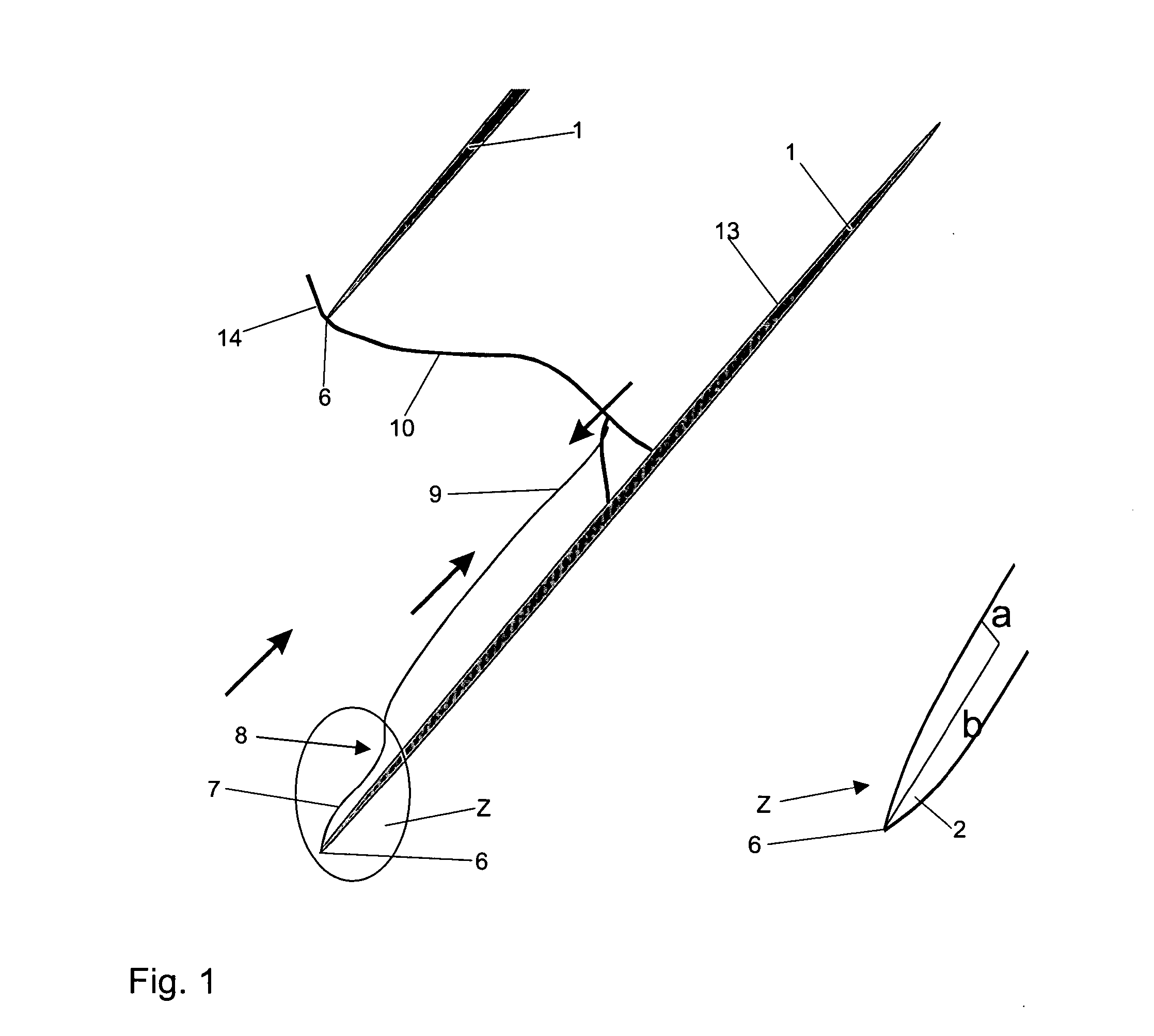
[0016] The compressor blades 1 illustrated in FIGS. 1 to 4 feature in an upper area, in relation to the blade tip 12, a specific form (2 to 5) of the blade leading edge 6 by which, as shown in FIG. 1, attachment of the leading edge shock wave 14 immediately at the blade leading edge 6 and, consequently, the boundary layer flow on the suction side 13 of the compressor blade 1 shown in FIG. 1 is achieved in this blade area. This means that the situation shown in FIG. 1 applies similarly to the compressor blades 1 shown in FIGS. 2 to 4.

[0017] According to the blade variant shown in FIG. 1, the blade leading edge has an elliptic (or also a parabolic) cross-sectional profile 2, with the ratio of the two semi-axes a / b being smaller than or equal to 1 / 4. This means that the curvature radius of the leading edge is small and the blade thickness correspondingly low. The cross-section of the compressor blade 1 is continuously curved.

[0018] In the case of the blade variant according to FIG. ...


PUM


Abstract

The compressor blades of an aircraft engine are, in at least one natural-vibration critical area, designed such that at the blade leading edge (6), the leading edge shock wave (14) attaches to the leading edge (6), as a result of which a laminar boundary layer flow (7) on the suction side (13) quickly transitions into a turbulent boundary layer flow (9) which is kept constant and prevented from re-lamination by the further, continuous curvature of the suction side. Therefore, the transition, whose periodic movement is also suppressed, cannot communicate with a suction-side compression shock (10), preventing the compression shock from augmenting the natural vibrations of the blade occurring under certain flight conditions. The blade leading edge can, for example, be designed as an ellipse with a semi-axis ratio equal to or smaller than 1:4.

Description

[0001] This application claims priority to European Patent Application EP 04090215.7 filed Jun. 2, 2004, the entirety of which is incorporated by reference herein. BACKGROUND OF THE INVENTION [0002] This invention relates to a compressor blade with reduced aerodynamic blade excitation, in particular for the fan of aircraft engines. [0003] Compressor blades with a large chord length used on certain types of aircraft-engine compressors are loaded to such an extent under certain operating conditions that damage to or life reduction of the compressor blade and the compressor disk may occur. [0004] In order to reduce the stressing of the compressor blades, the assignee of the present application has previously filed a U.S. patent application on Apr. 5, 2004, to Erik Johann, entitled “COMPRESSOR FOR AN AIRCRAFT ENGINE”, in which it was disclosed to provide a flow transition fixation means in the form of a surface roughness applied to the suction side of the blade at a certain distance fro...

Claims


Application Information

Patent Timeline
IPC IPC(8): F01D5/26F01D5/14B63H1/16F01D5/16
CPCF01D5/141F01D5/145F01D5/16F01D25/06F04D29/324F05D2240/121F05D2240/122F05D2240/303F05D2240/304Y02T50/673F05D2240/30F05D2250/16F05D2250/611F05D2250/14F04D29/681Y02T50/60
Inventor JOHANN, ERIK
Owner ROLLS ROYCE DEUT LTD & CO KG
Learn More