Variable laminoplasty implant

Active Publication Date: 2005-12-08
DEPUY SPINE INC (US)
View PDF21 Cites 103 Cited by
  • Summary
  • Abstract
  • Description
  • Claims
  • Application Information

AI Technical Summary

Benefits of technology

[0012] Consequently, an improved implant is provided that can be used in a laminoplasty procedure without requiring the intensive customization of a bone plate or the selection from a wide size variet

Problems solved by technology

The constriction of the spinal cord in the cervical spine, for example, often produces pain, weakness, or loss of feeling in extremities.
Other causes for narrowing of the spinal canal include disc shrinkage, which causes the disc space to narrow and the annulus to bulge and mushroom out, resulting in pressure on the spinal cord.
Degenerative arthrit

Method used


Image

  • Variable laminoplasty implant
  • Variable laminoplasty implant
  • Variable laminoplasty implant

Examples


Embodiment Construction

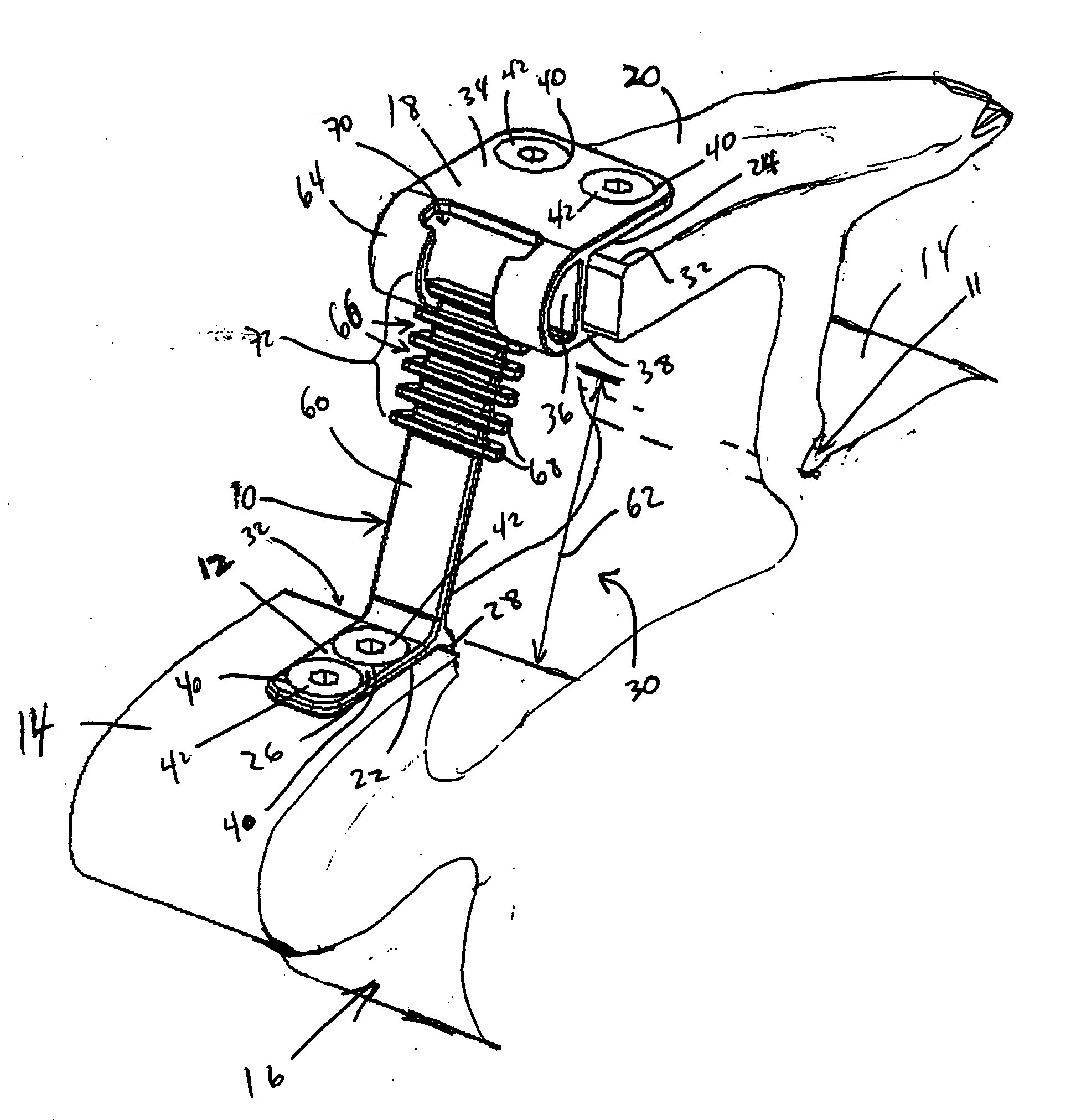
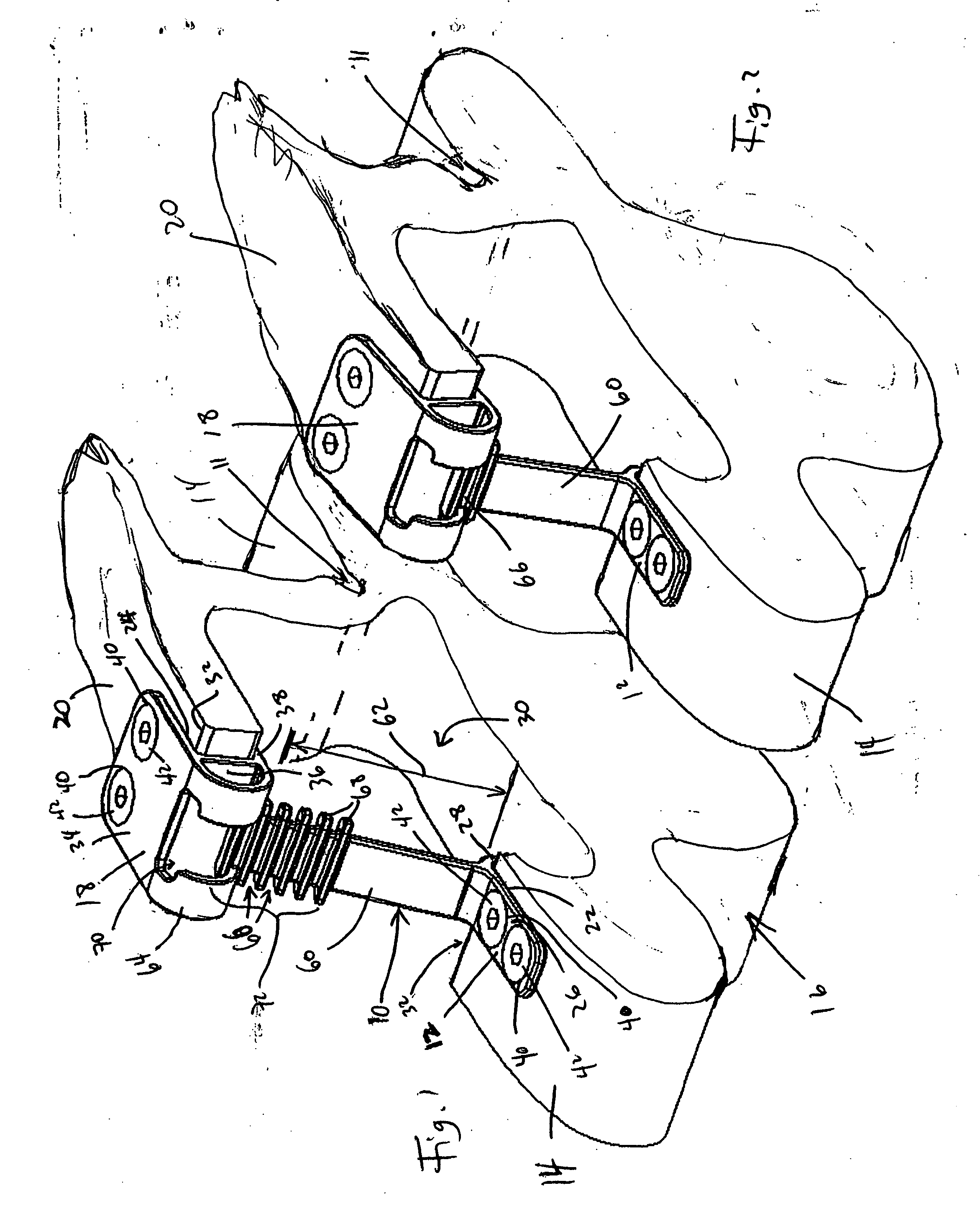
[0019] Referring to FIG. 1, in a preferred laminoplasty procedure, an osteotomy is performed in which a complete cut is made through vertebra 16, approximately between the lamina 20 and lateral mass 14, such as the articular mass or facet portion therof. A partial-depth cut 11 is made on the opposite lateral side, also approximately between the lamina 20 and other lateral mass 14. The lamina 20 is then hinged open about the partial cut 11 to increase the cross-sectional size of the spinal canal to decompress the spinal cord therein.

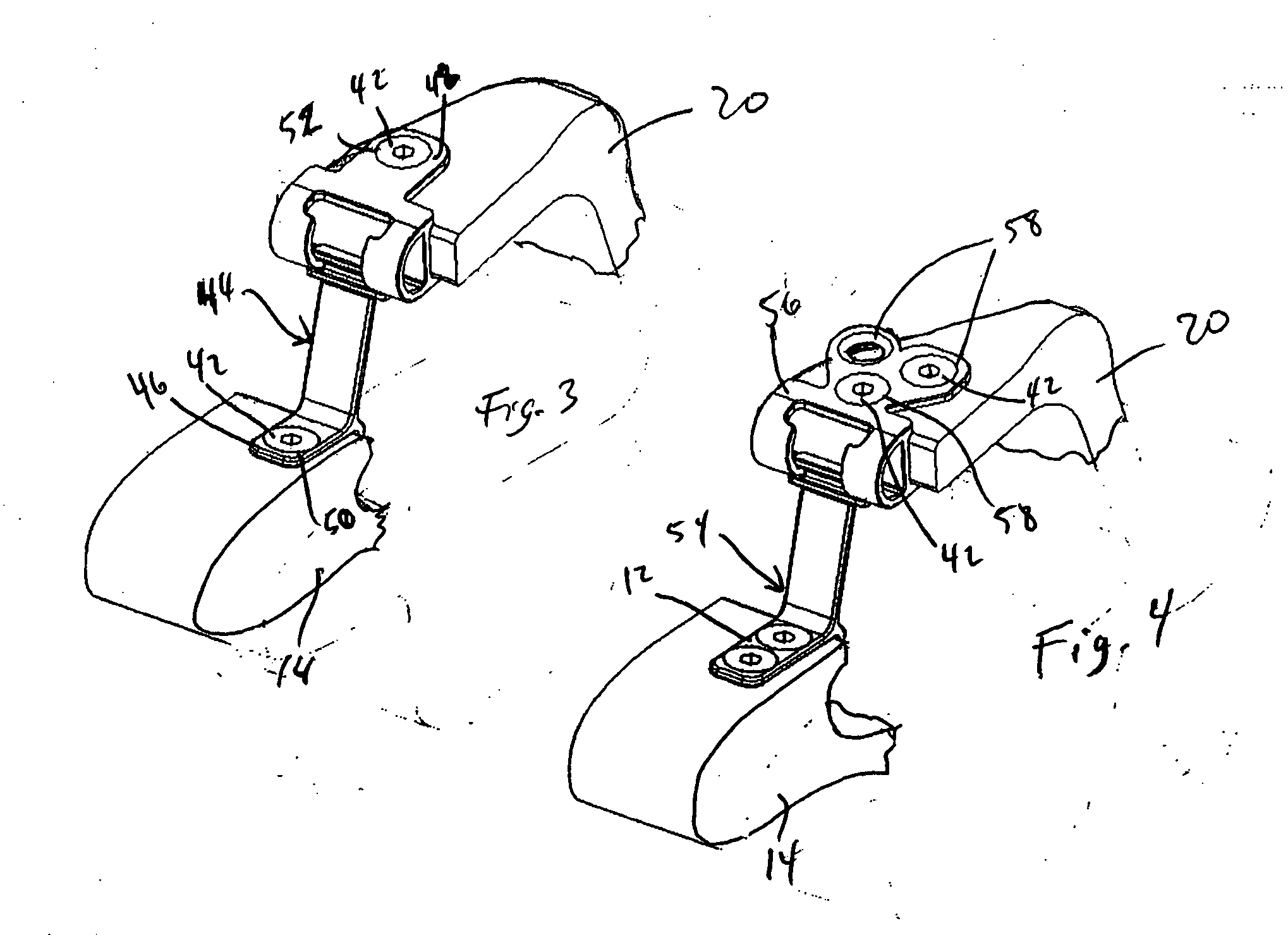
[0020] A preferred embodiment of a laminoplasty implant 10 includes a lateral base 12 that is configured for securing to a lateral mass 14 of a vertebra 16. A lamina base 18 is configured for securing to a portion of a lamina 20 that has been cut and hinged away from the lateral mass 14. For alternative surgical procedures, the base can be configured for securing to different parts of the vertebra, a differently prepared vertebra, or to different bones, ...


PUM


Abstract

A vertebral implant comprising a first base configured for securing to a first cut portion of a vertebra, and second base configured for securing to a second cut portion of the vertebra. A connecting member is configured to associate the first and second bases at a preselected spacing from each other, and the implant is preferable adjustable to select the spacing.

Description

FIELD OF THE INVENTION [0001] The present invention relates to an implant for bone surgery, and more specifically to a vertebral implant with an adjustable configuration. BACKGROUND OF THE INVENTION [0002] In certain pathologies, the spinal canal extending through a patient's vertebrae is or becomes too narrow and constricts the spinal cord extending therethrough. The narrowing may be congenital, potentially affecting patients at any age. Narrowing can also be attributable to other causes, such as age, injury or removal of a spinal disk. [0003] A condition associated with aging, for instance, is spondylolsis, in which intervertebral disc loose water and become less dense. These degenerative changes near the disk can cause an overgrowth of the bone, producing bony spurs called, “osteophytes” that can compress the spinal cord. The constriction of the spinal cord in the cervical spine, for example, often produces pain, weakness, or loss of feeling in extremities. Other causes for narro...

Claims


Application Information

Patent Timeline
IPC IPC(8): A61B17/58A61B17/70
CPCA61B17/7035A61B17/7044A61B17/7071A61B17/58A61F2/28
Inventor TAYLOR, BRETT ALLISON
Owner DEPUY SPINE INC (US)
Why Eureka
Try Eureka