
System and method for building a component base architecture

a technology of component architecture and programming structure, applied in the direction of program control, instruments, digital transmission, etc., can solve the problems of unwanted temporal and financial costs, difficult and expensive for an enterprise to locate and retain the necessary expertise, programmer or programmers, etc., to reduce the cost and time needed, accelerate the development of architectures for multiple environments, and facilitate the user of the development environmen

Inactive Publication Date: 2005-12-08
LONG MICHAEL V
View PDF9 Cites 76 Cited by
  • Summary
  • Abstract
  • Description
  • Claims
  • Application Information

AI Technical Summary

Benefits of technology

[0028] In one embodiment of the invention, a refined 3D graphical interface allows users to build and test scripts on the fly without keying in lines of program code.
[0031] One feature of the present invention is the novelty of the component framework. A component framework comprises a component wrapper to abstract the interconnections made by the underlying component binaries. This abstraction is advantageously exploited by the development environment to provide more direct control over component interactions and relationships. In this manner, the development environment can employ such novel features as automatically identifying components having compatible interfaces, which relieves the user of the development environment from the burden of having previous knowledge of programming and knowledge of the components. The abstraction allows a user to manipulate component interactions even while a script is running. The component wrappers are still further abstracted to an interface description file which describes the interface of the component wrapper.
[0032] The present invention can be used to develop component-based scripts and architectures in any of the information technology zones, greatly reducing the cost and amount of time needed to develop a program. Still, it would be advantageous to be able to share logic components between different development zones to quickly and efficiently develop architectures for multiple environments.

Problems solved by technology

Unwanted temporal and financial costs can be attributed to the excessive time to learn these individual tools and become skilled in their operation.
It is difficult and expensive for an enterprise to locate and retain the necessary expertise in each of the different technology fields.
Yet many of these tools still require a programmer or team of programmers to learn multiple languages.
Not only do languages have different programmatic syntaxes, but also their underlying fundamentals are often dissimilar.
The more languages that a programmer must learn, the more unwanted financial and temporal costs can be attributed with creating software programs.
Long and complex development cycles are required to develop the software, resulting in greatly increased cost for investing in information technology.
Another problem associated with existing development environments is the lack of code reuse.
There is no way of accessing these objects for multiple programs.
However, these environments still require extensive programming, and all require a knowledge of programming to operate.
Unwanted temporal and financial costs persist even with the benefits of visual programming IDEs.
However, these COP environments have many drawbacks.
However, there are several drawbacks of this system.
Firstly, the system limits a programmer to designing only applets or application programs because deployment is dependent on the development environment.
Secondly, the system of the '218 patent does not use an intuitive and efficient user interface.
For example, looking at FIG. 16 of the '218 disclosure, a very simple applet is created using components, yet it is very difficult to decipher the operations of each component.
The “wire” connectors between components are already difficult to trace.
Furthermore, if a component has several dozen or more “connectors”, it becomes very difficult to display these connectors in conjunction with the component icon.
Thirdly, the development environment is inefficient and overly complex.
This separation of the physical and logical views is a drawback.
However, this method is overly complex since it includes both a physical component description and a logical component description.
Still, there are several drawbacks with such a definition.
Firstly, the COP language is limited to describing the JAVA BEAN architecture.
Such a limitation disregards a significant design feature of component programming, which is the use of components without consideration for its encapsulated code.
Secondly, the COP language does not support event-binding between components of multiple languages.
The COP language does not sufficiently abstract the interconnections made by the underlying components.
Consequently, it becomes very difficult or virtually impossible for a development environment to identify components having compatible interfaces, which is further made problematic when working with components programmed in multiple languages.
Such a drawback would place additional unwanted and costly demands on the user or programmer to have prerequisite knowledge of the components.
Thirdly, because an uncompilable markup language defines the COP language, a program cannot flexibly be deployed to a native language or environment, or multiple languages and multiple environments, which provides obvious advantages.
That is, the COP language does not provide any type of compilation or deployment instructions.

Method used


Image

  • System and method for building a component base architecture
  • System and method for building a component base architecture
  • System and method for building a component base architecture

Examples


Embodiment Construction

[0056] In the following detailed description of one embodiment of the invention, reference is made to the accompanying drawings, which form a part hereof, and in which is shown by way of illustration of a specific embodiment in which the invention may be practiced. This embodiment is described in sufficient detail to enable one skilled in the art to practice the invention. It will be understood that other embodiments may be utilized and that structural changes may be made without departing from the spirit and scope of the present invention. The following detailed description is, therefore, not to be taken in a limiting sense.

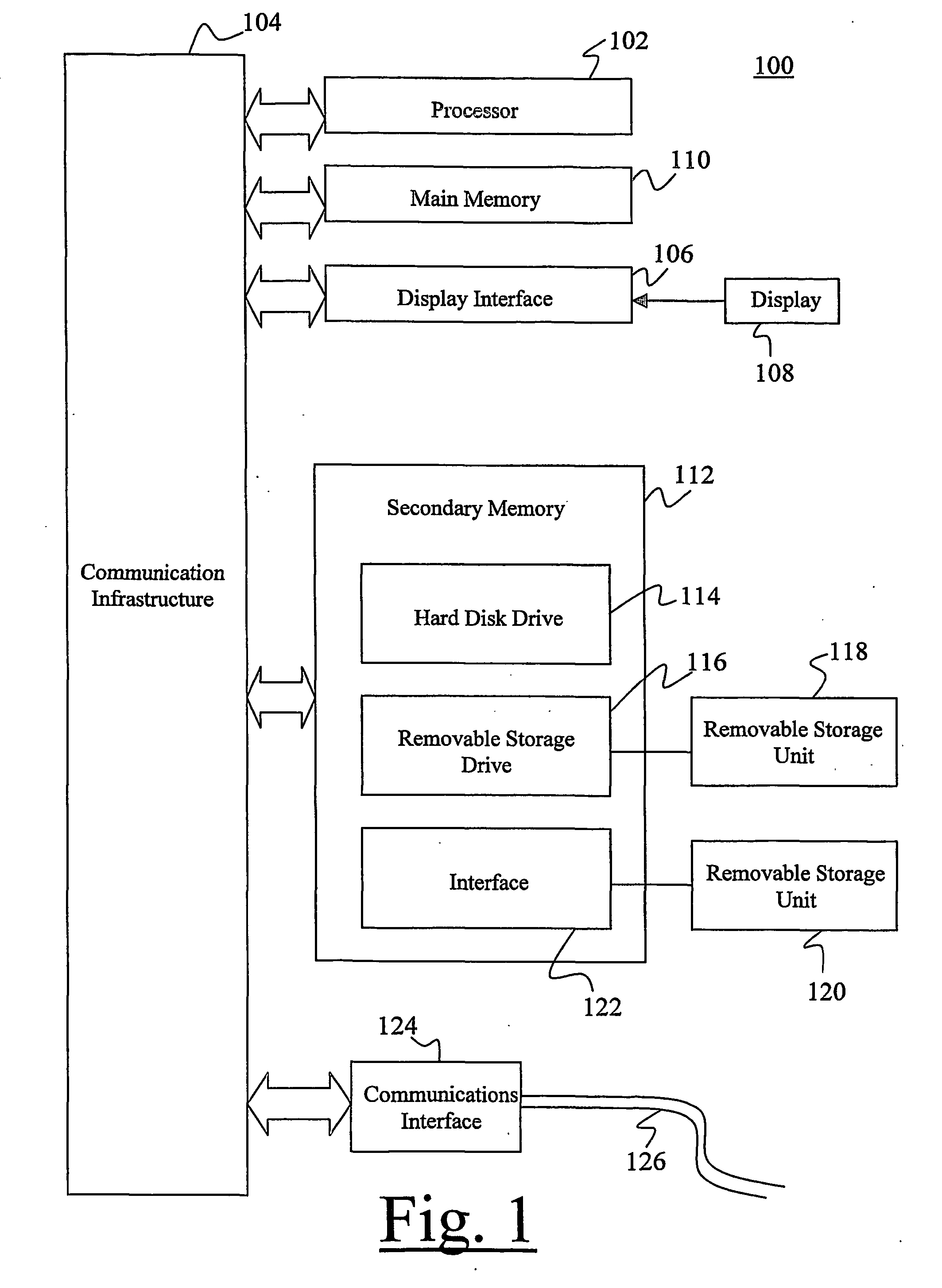
[0057] The present invention may be implemented using hardware, software or a combination thereof and may be implemented in one or more computer systems or other processing systems. In fact, in one embodiment, the invention is directed toward one or more computer systems capable of carrying out the functionality described herein. An example of a computer system...


PUM


Abstract

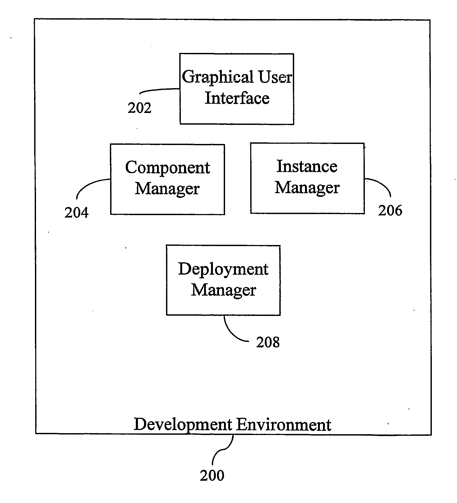
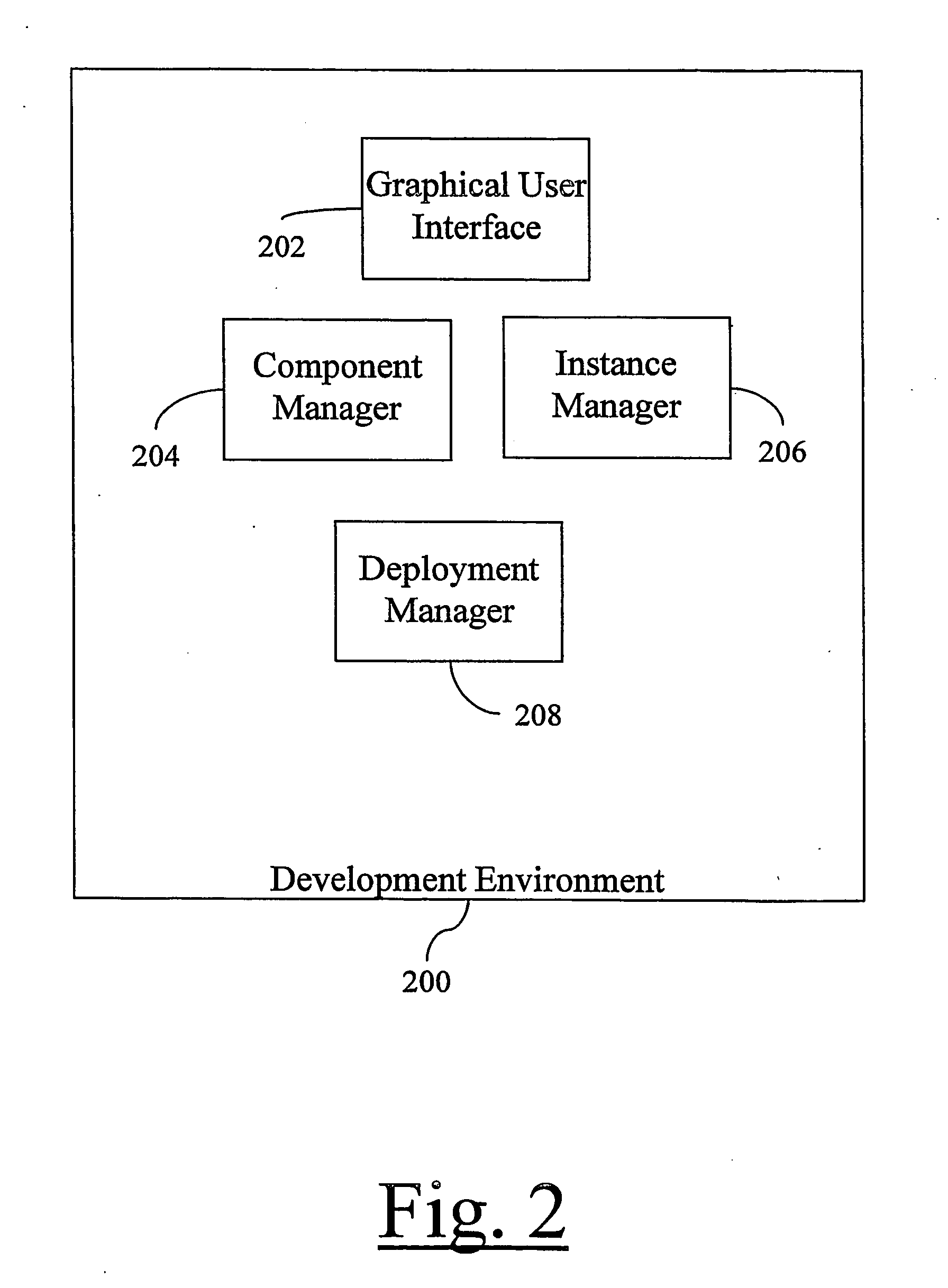
A system and method for building a component-based architecture. One or more software components (1401) are registered with a component-based architecture development environment (200) in accordance with an interface definition file (1406). The interface definition file (1406) identifies one or more methods invocable by the associated component's encapsulated code. The development environment (200) enables a user to select the one or more methods for defining component-to-component relationships in a script configured in a hierarchal tree format.

Description

FIELD OF THE INVENTION [0001] This invention generally relates to the field of software development tools, and more specifically to development tools using component-oriented programming constructs. BACKGROUND OF THE INVENTION [0002] While there are innumerable programming environments at the disposal of a computer programmer, the general evolution of programming environments has been relatively disjointed. Over time, a large variety of programming languages have been developed and employed for different tasks. For example, as a non-exhaustive list, the C programming language family, including C, C+, C++, and C#, primarily have been used to author desktop, server, or distributed computer applications, as has BASIC, PASCAL, ADA, TCK / TL, CORBA, and JAVA. For general use in network applications, computer programming languages such as the script languages, including JAVASCRIPT, VBSCRIPT, ASP, and PHP are most appropriate. For interaction with databases and repositories, SQL is the defac...

Claims


Application Information

Patent Timeline
IPC IPC(8): G06F9/44H04L29/06H04L29/08
CPCG06F8/20G06F8/36H04L69/329H04L67/34H04L67/02H04L29/06H04L9/40
Inventor LONG, MICHAEL V.
Owner LONG MICHAEL V
Learn More