Cryogenic fluid dispensing system

a cryogenic fluid and dispensing system technology, applied in the direction of container discharging methods, container filling under pressure, vessel construction details, etc., can solve the problems of increasing the heat leakage to the stored cryogen, and reducing the efficiency of discharging

Inactive Publication Date: 2005-12-15
CHART INC
View PDF17 Cites 54 Cited by
  • Summary
  • Abstract
  • Description
  • Claims
  • Application Information

AI Technical Summary

Problems solved by technology

The structural reinforcements required to ensure durability of transportable storage cylinders, however, provide additional heat conduction paths and increase the heat in-leak to the stored cryogen.
In addition, transporting the tanks can be costly.
The bulk tank must be mounted on the vehicle, however, in a generally horizontal orientation which results in a large liquid surface area beneath the tank head space.
This makes pressure-building very difficult as the vapor from the heat exchanger tends to be condensed by the large liquid surface area.
As a result, the system operator must wait a long time for pressure to build which results in long delivery times.
Venting of the bulk tank is undesirable as it takes additional time, decreases the amount of product available for distribution and increases waste.
A further disadvantage of such a system is that the entire contents of the bulk tank are heated even though only a portion is dispensed.
This decreases the hold time of the tank which results in increased vent losses.
Furthermore, the high pressure contained by the bulk tank requires that it have very thick inner walls which increases the system expense and weight.
A disadvantage of such an arrangement, however, is that the pump is exposed to ambient air and temperature.
As a result, the pump must be equipped with seals that have high maintenance requirements.
In addition, the pump must be cooled down prior to use or else two-phase flow of cryogen will occur in the pump and damage it.
This results in a significant delay before dispensing may take place.
The meter sump does not contain liquid cryogen, however, when the system travels between dispensing locations.
As a result, the meter must be cooled down which causes a delay prior to dispensing.
In addition, the pump, the electrical generation system, recirculation piping and meter sump add to the size, weight, complexity and expense of the system.
The pump and electrical generation system also adds maintenance and operating costs to the system.
A further disadvantage is that such a system can't be used to dispense liquid oxygen.
This is because the electric pump motor and electrical feeds cannot be submerged in liquid oxygen in the sump due to ignition concerns.

Method used


Image

  • Cryogenic fluid dispensing system
  • Cryogenic fluid dispensing system
  • Cryogenic fluid dispensing system

Examples


first embodiment

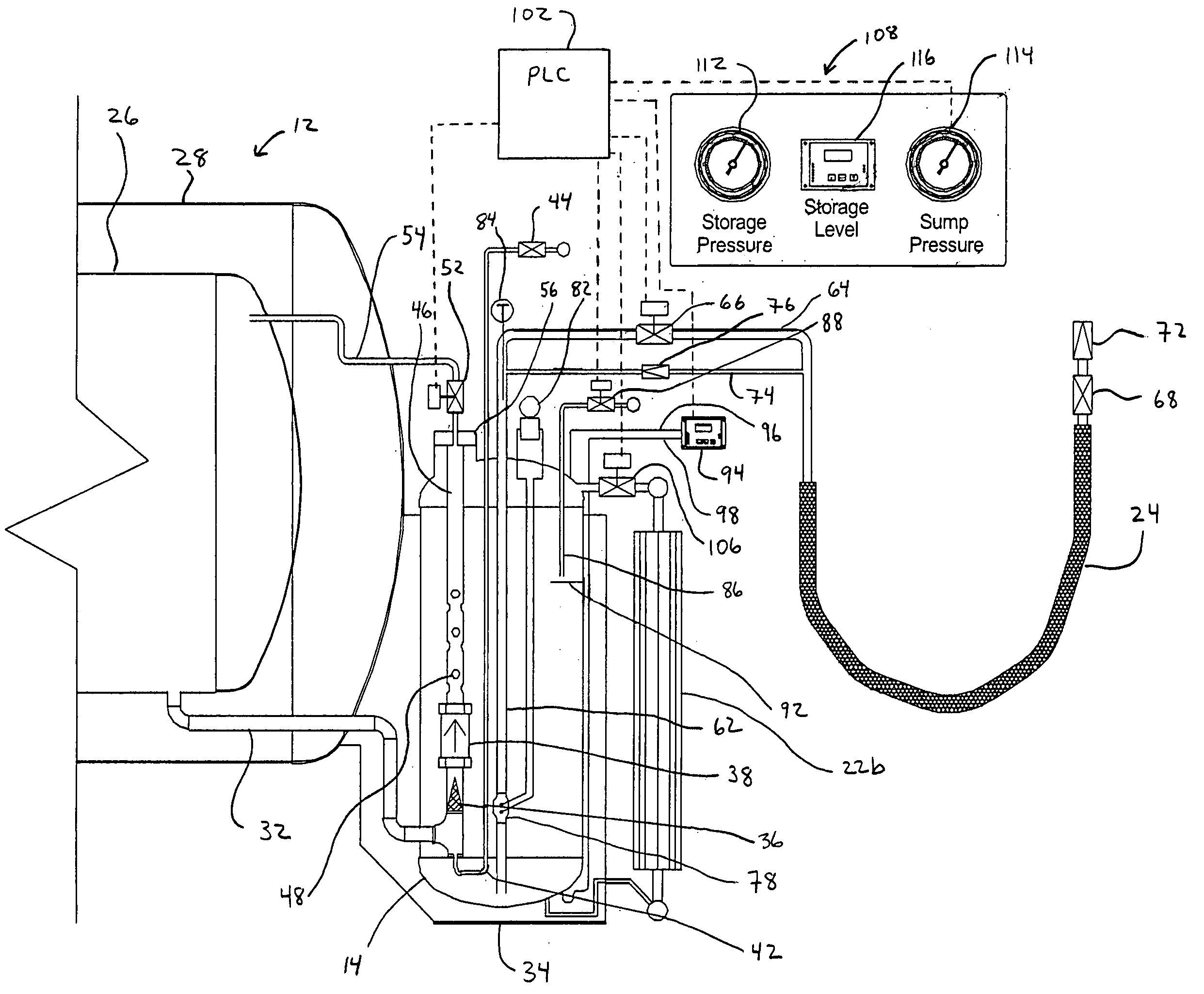
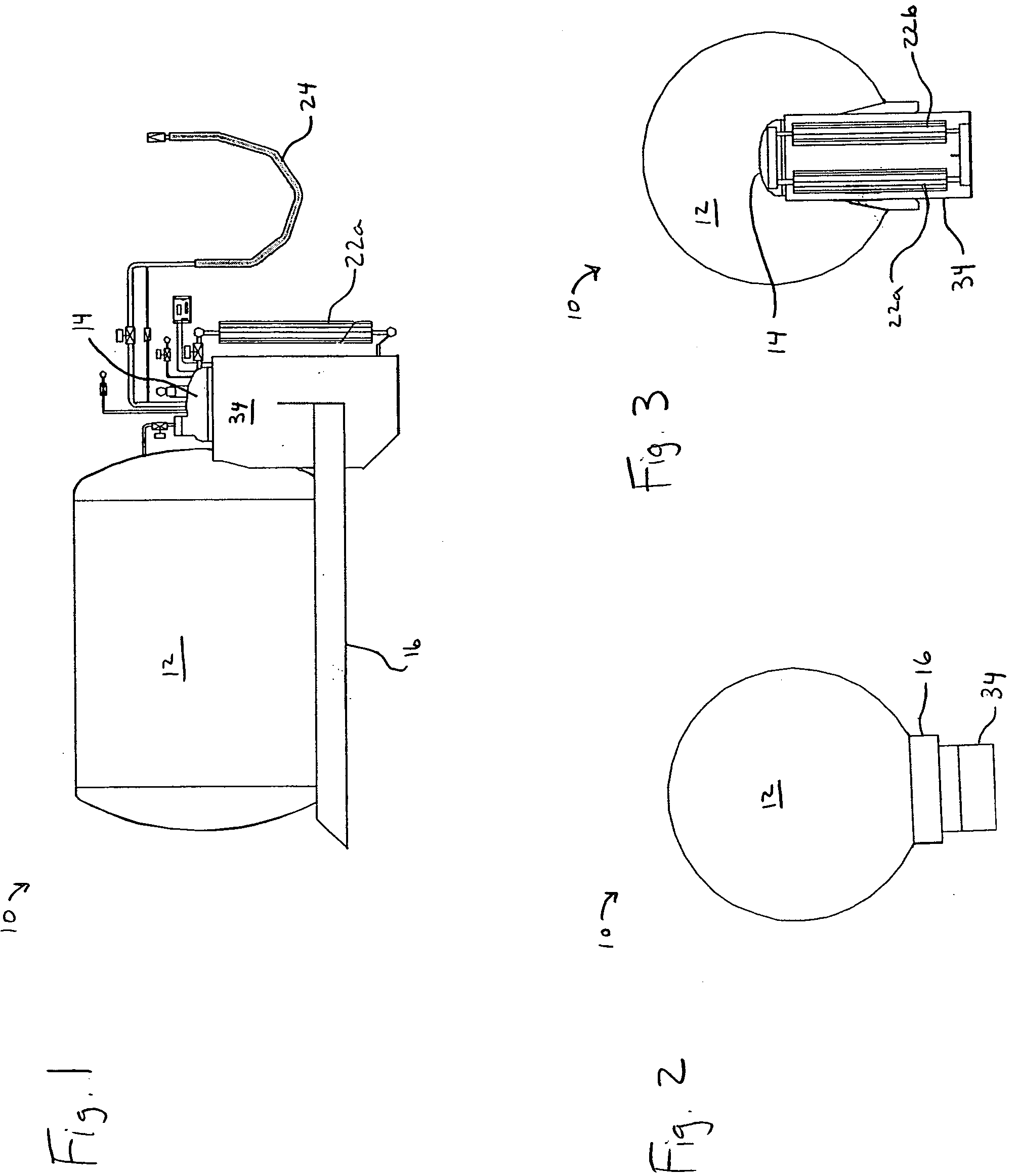
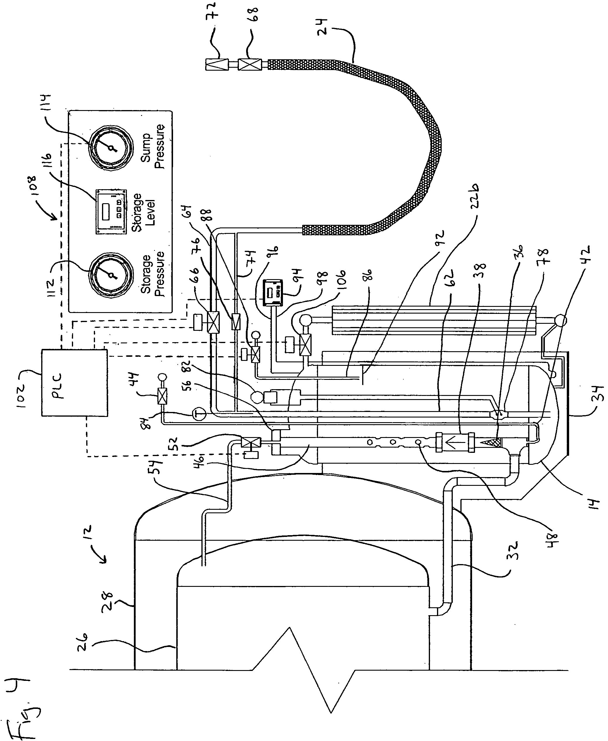
[0032] the system of the present invention is indicated in general at 10 in FIGS. 1-3. The system features a jacketed bulk tank 12 and pulse tank or sump 14. Low pressure bulk tank 12 preferably has a volume of approximately 1000 gallons while sump 14 preferably has a volume of approximately 300 liters. Such a capacity will permit the system to fill both one and multiple cylinders at a use point without refilling the sump. A bulk tank size of 2000 gallons with a sump volume of 500 liters are preferred if larger delivery amounts are contemplated.

[0033] While the bulk tank 12 is low pressure, sump 14 preferably has a maximum allowable working pressure of approximately 500 psi. The delivery pressure of the system will typically be approximately 50 psi above the pressure of the receiving vessel. As a result, the system can dispense liquid to a 400 psi container such as those used for laser welding.

[0034] The bulk tank 12 and sump 14 are mounted on a frame 16. Frame 16 preferably is mou...

second embodiment

[0059] the system features a vent circuit or stack, indicated in general at 233 in FIG. 7, that communicates with the head space of bulk tank 212. The vent stack is provided with emergency pressure relief valves 234 that automatically open to vent the bulk tank when the pressure therein reaches a predetermined maximum level. In addition, the vent stack includes a muffler 235 that communicates with the head space of the bulk tank through main storage road relief valve 236 and main storage vent valve 237, both of which are preferably manually operated valves. The muffler preferably is constructed from a steel tube filled with brass wool. The brass wool slows the gas flow through the muffler so that is quieted. The sump tank vent line 239 and valve 240 communicate with the muffler 235 as well.

[0060] As illustrated in FIG. 7, the second embodiment of the system of the present invention also differs from the first embodiment in that the sample tube 242 communicates with the bottom of the...


PUM


Abstract

A mobile system for dispensing cryogenic liquid to a use point includes a low pressure bulk tank containing a supply of cryogenic liquid and a high pressure sump in communication with the bulk tank so as to receive cryogenic liquid therefrom. A check valve is in circuit between the bulk tank and the sump. A heat exchanger is in communication with the sump and selectively receives and vaporizes a portion of cryogenic liquid from the sump when the sump is full as detected by a liquid level sensor. The resulting vapor is directed to the sump so as to increase the pressure therein. The check valve closes when the pressure building within the sump is initiated. The pressurized cryogenic liquid is dispensed from the sump via a dispensing hose. Operation of the system valves is automated by a controller.

Description

CLAIM OF PRIORITY [0001] This application claims priority to U.S. Provisional Patent Application Ser. No. 60 / 557,775, filed Mar. 30, 2004, currently pending.BACKGROUND OF THE INVENTION [0002] The present invention generally relates to delivery and dispensing systems for cryogenic fluids and, more specifically, to a mobile cryogenic liquid dispensing system that allows for dispensing of cryogenic liquid directly to a use point without the use of a pump. [0003] Cryogenic liquids are typically stored in thermally insulated tanks which consist of an inner storage vessel mounted within, and thermally isolated from, an outer shell. In addition, cryogenic liquids are usually dispensed from a bulk supply tank to smaller storage cylinders for use in various applications including industrial, medical and research processes. [0004] Oftentimes, the cryogenic liquid bulk supply tank remains stationary and the storage cylinders are transported to the bulk supply, refilled and transported back to ...

Claims


Application Information

Patent Timeline
Patent Type & Authority Applications(United States)
IPC IPC(8): F17C5/02F17C9/02F17C13/00F17C13/02
CPCF17C13/025F17C13/026F17C2205/0107F17C2205/0126F17C2205/0157F17C2205/0335F17C2205/0364F17C2205/0376F17C2221/01F17C2221/03F17C2223/0161F17C2223/033F17C2223/046F17C2225/0161F17C2225/035F17C2225/036F17C2227/0311F17C2227/0393F17C2250/01F17C2250/032F17C2250/0417F17C2250/043F17C2250/0439F17C2250/0443F17C2265/063F17C2270/01F17C5/02F17C9/02F17C13/021
Inventor DRUBE, PAULNEESER, TIMOTHYLINDQUIST, TROY
Owner CHART INC
Why Eureka
Try Eureka