

Hybridization detecting unit including an electrode having depression parts and DNA chip including the detecting unit
a detection unit and electrode technology, applied in the field of hybridization detection technique, can solve the problems of long time-consuming and laborious operation of dna probes or the like for fixing nucleic acids for detection, and the amount of detected hybridization is non-uniform, so as to achieve efficient integration (fix) gene information and short time-consuming hybridization progress
- Summary
- Abstract
- Description
- Claims
- Application Information
AI Technical Summary
Benefits of technology
Problems solved by technology
Method used
Image

Examples
first embodiment
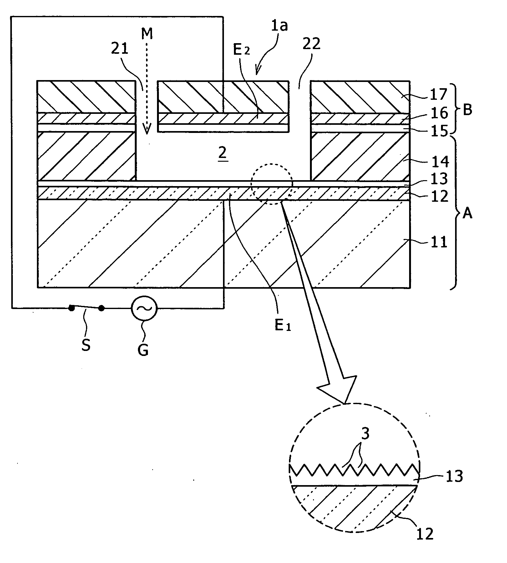
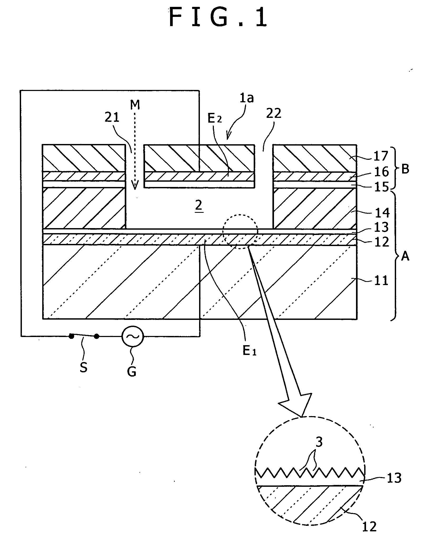
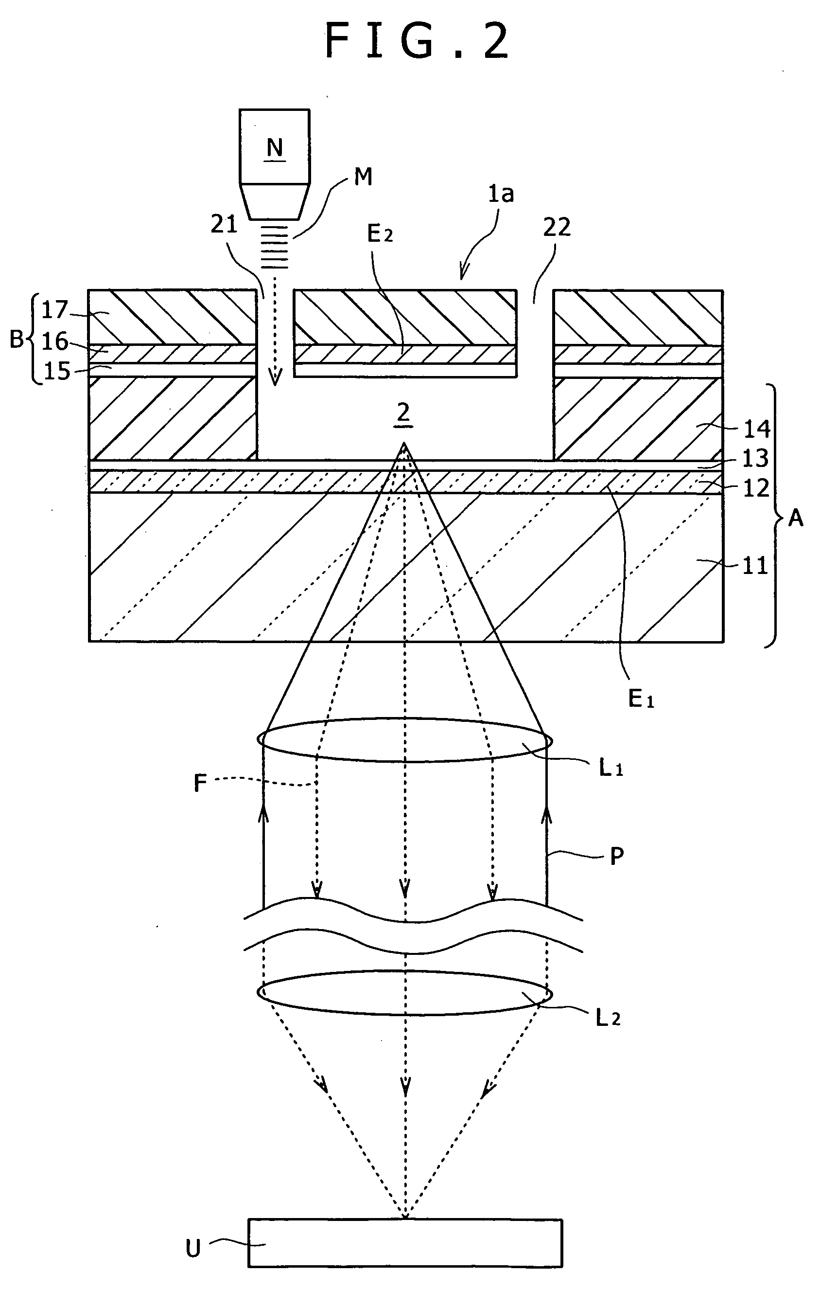
[0061]FIG. 1 is a sectional view of a structure of principal parts of a hybridization detecting unit (hereinafter abbreviated to a “detecting unit”) according to the present invention. FIG. 2 is a diagram schematically showing a structure of medium supplying means and optical pickup means for the detecting unit 1.
[0062] Reference 1a in FIG. 1 indicates a form of principal parts of the detecting unit. A DNA chip according to an embodiment of the present invention can be obtained by forming or arranging the detecting units 1a on a substrate.
[0063] The detecting unit 1a includes a lower side substrate A and an upper side substrate B placed on the lower side substrate A. The lower side substrate A includes a base material layer 11, a conductor layer 12 laminated on the base material layer 11, an insulating layer 13 laminated on the conductor layer 12, and a surface layer 14 laminated on the insulating layer 13 and having a well-shaped reaction area 2 formed by a predetermined surface t...
second embodiment
[0092]FIG. 13 is a sectional view of a structure of principal parts of a detecting unit according to the present invention.
[0093] A detecting unit 1b according to the second embodiment is characterized in that one of opposed electrodes (E1 in this case) is formed so as to have a smaller surface area than the electrode (E2 in this case) on the other side.
[0094] This structure makes an electric field (lines of electric force) more concentrated and thus a non-uniform electric field formed at the electrode E1 having the smaller surface area (see reference Z in FIG. 13). Therefore nucleic acid molecules are moved toward the electrode E1 by dielectrophoresis. FIG. 13 schematically shows, as a typical example, a state in which nucleic acid D for detection in a free state is being moved toward the electrode E1.
[0095] Thus, nucleic acid molecules spread widely in a free state within the reaction area 2 can be collected in a region around the electrode E1, whereby concentration of the nucle...
third embodiment
[0096]FIG. 14 is a sectional view of a structure of principal parts of a detecting unit according to the present invention. In FIG. 14, a sectional view as viewed along a line II-II in the figure is added (see a lower diagram in FIG. 14).
[0097] A detecting unit 1c according to the third embodiment is characterized in that opposed electrodes E3-E4 are allocated on a left and a right of a reaction area 2. FIG. 15 shows a modification of the detecting unit 1c which modification is characterized in that an electrode (E3 in this case) used as an electrode to which to draw nucleic acid molecules is formed so as to have a smaller surface area than another electrode E4.
[0098] As in the above-described detecting unit 1b, in this modification shown in FIG. 15, an electric field is more concentrated and thus a non-uniform electric field is formed at the electrode E3 having the smaller surface area (see lines of electric force Z in FIG. 15). Therefore nucleic acid molecules (nucleic acid D for...
PUM
| Property | Measurement | Unit |
|---|---|---|
| frequency electric field | aaaaa | aaaaa |
| depth | aaaaa | aaaaa |
| electric field | aaaaa | aaaaa |
Abstract
Description
Claims
Application Information