Actuator and its control method and lens device

a technology of actuator and control method, applied in piezoelectric/electrostrictive/magnetostrictive devices, mountings, instruments, etc., can solve the problems of large attenuation rate, unfavorable responsiveness of the lens-barrel, and inability to accurately move the lens-barrel, etc., to achieve accurate movement, accurate movement, accurate movement

Inactive Publication Date: 2005-12-15
FUJI PHOTO OPTICAL CO LTD
View PDF11 Cites 40 Cited by
  • Summary
  • Abstract
  • Description
  • Claims
  • Application Information

AI Technical Summary

Benefits of technology

[0047] The invention according to a twenty-first aspect is, in the invention of the nineteenth aspect, characterized in that the position detector is a reflection type photo-reflector with a reflection surface formed on the driven member. According to the invention of the twenty-first aspect, the reflection surface of the photo-reflector is formed on the driven member. Therefore, the installation space for the position detector can be made small, and thus the lens device can be made compact.
[0048] According to the actuator of the present invention, the driven member is held from both sides by the driving members, and therefore, the frictional forces of the driven member and the driving members are obtained stably, thus making it possible to move the driven member accurately. According to a control method of the actuator according to the present invention, the timings become equal among the plurality of piezoelectric elements on the occasion of a slow deforming speed of the piezoelectric elements, while on the occasion of a high deforming speed, the timings are made to differ among the plurality of piezoelectric elements. Therefore, moving and stopping of the driven member can be reliably performed, and the driven member can be accurately moved.
[0049] According to the method for controlling the actuator according to the present invention, voltage is applied so that the deforming speed differs at the time of extension and the time of contraction of the piezoelectric element, and the timings are equal among the plurality of piezoelectric elements on the occasion of the slow deforming speed, while on the occasion of the high deforming speed, the timings are made to differ among the plurality of piezoelectric elements. Therefore, the driven member can be accurately moved.
[0050] According to the actuator of the present invention, the frictional engaging surfaces of the driven member with the driving members, which are formed on both sides of the driven member, are not parallel, and therefore, rattle of the driven member and the driving members can be prevented by holding the driven member from both sides by the driving members.
[0051] According to the actuator of the present invention, the driving member and the driven member are brought into point contact or line contact, and therefore, substantially constant frictional forces can be applied between the driving members and the driven member, and the driven member can be always moved accurately.
[0052] Further, according to the lens device of the present invention, the position detector is provided by utilizing the driven member provided to extend in the driving direction. Therefore, the displacement amount of the lens device can be accurately measured, and the lens device can be made compact.

Problems solved by technology

However, the actuator described in Japanese Patent No. 2633066 transmits a driving force via the long driving rod, and therefore, vibration of the piezoelectric element is absorbed by the driving rod and attenuated, thus causing the problem of being unable to move the lens-barrel accurately.
The vibration at a high frequency especially has a large attenuation rate by the driving rod, and therefore, responsiveness of the lens-barrel becomes unfavorable.
Therefore, the actuator in Japanese Patent No. 2633066 can be controlled only with the driving pulse at a low frequency, thus causing the problem of the number of moving times of the lens-barrel per unit time becoming small.
Therefore, in Japanese Patent Application Laid-open No. 2000-50660, a boosting device becomes necessary, thus causing the problems of the device becoming large in size, and requiring a complicated control.
Accordingly, there is the problem that selection of the spring force which frictionally engages the driven member and the driving member with a suitable frictional force is extremely difficult.
Especially in Japanese Patent Application Laid-open No. 10-232337, the spring force is generated by the shape of the driving member (engaging member), and therefore, it is very difficult to set the suitable spring force.
In the actuator disclosed in Japanese Patent Application Laid-open No. 10-232337, the movable plate is held from both sides with the engaging member to be frictionally engaged, and there is the problem that a rattle occurs to the movable plate in the direction orthogonal to the holding direction.
Therefore, there arises the problem that the movable plate (driven member) cannot be accurately moved.
Further, the actuators disclosed in Japanese Patent No. 2633066, Japanese Patent Application Laid-open No. 2000-50660, and Japanese Patent Application Laid-open No. 10-232337 have the problem that the frictional forces between the driving member (the above described driving rod, engaging member and the like) and the driven member (the above-described lens-barrel, moving plate and the like) easily become unstable.
Especially when machining accuracy of the driving member and the driven member is low, there is the possibility that the aforesaid frictional force changes in accordance with the contact position of the driven member and the driving member, and the frictional force changes in accordance with the individual actuators.
Therefore, the conventional actuators have the problem that it is difficult to move the driven member stably and accurately.
The photo-interrupter and the photo-reflector themselves are very compact, but a shielding body and a reflection plate are large, and thus causing the problem that the lens device becomes large in size.

Method used


Image

  • Actuator and its control method and lens device
  • Actuator and its control method and lens device
  • Actuator and its control method and lens device

Examples


first embodiment

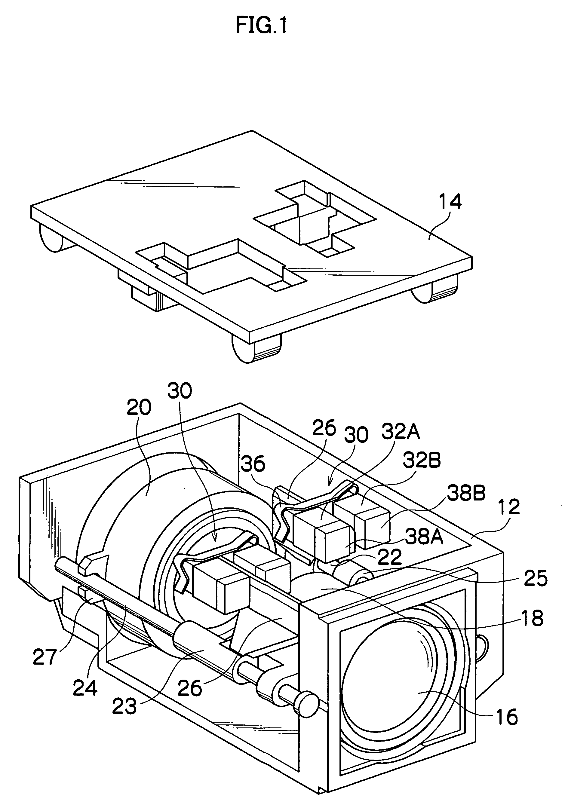
[0076]FIG. 1 is a perspective view showing a construction of the lens device to which an actuator of a first embodiment is applied. The lens device shown in the drawing has a box-shaped case constituted of a case body 12 and a lid 14, and a fixed lens 16 is mounted to a side surface of the case body 12.

[0077] Two lens frames 18 and 20 are provided inside the case body 12, and movable lenses such as a zoom lens and focus lens are held in these two lens frames 18 and 20. The two lens frames 18 and 20 are supported slidably in an optical axis direction by two guide rods 22 and 24 placed parallel with the optical axis of the fixed lens 16. Namely, a guide part 23 is formed to project on the outer peripheral surface of the lens frame 18. The guide rod 24 is inserted through a through-hole of this guide part 23 and guided, and the guide rod 22 is engaged in a U-shaped groove of an engagement part (not shown) formed to project on an opposite side from the guide part 23, whereby the lens fr...

second embodiment

[0098] Next, an operation of the actuator of the second embodiment will be explained.

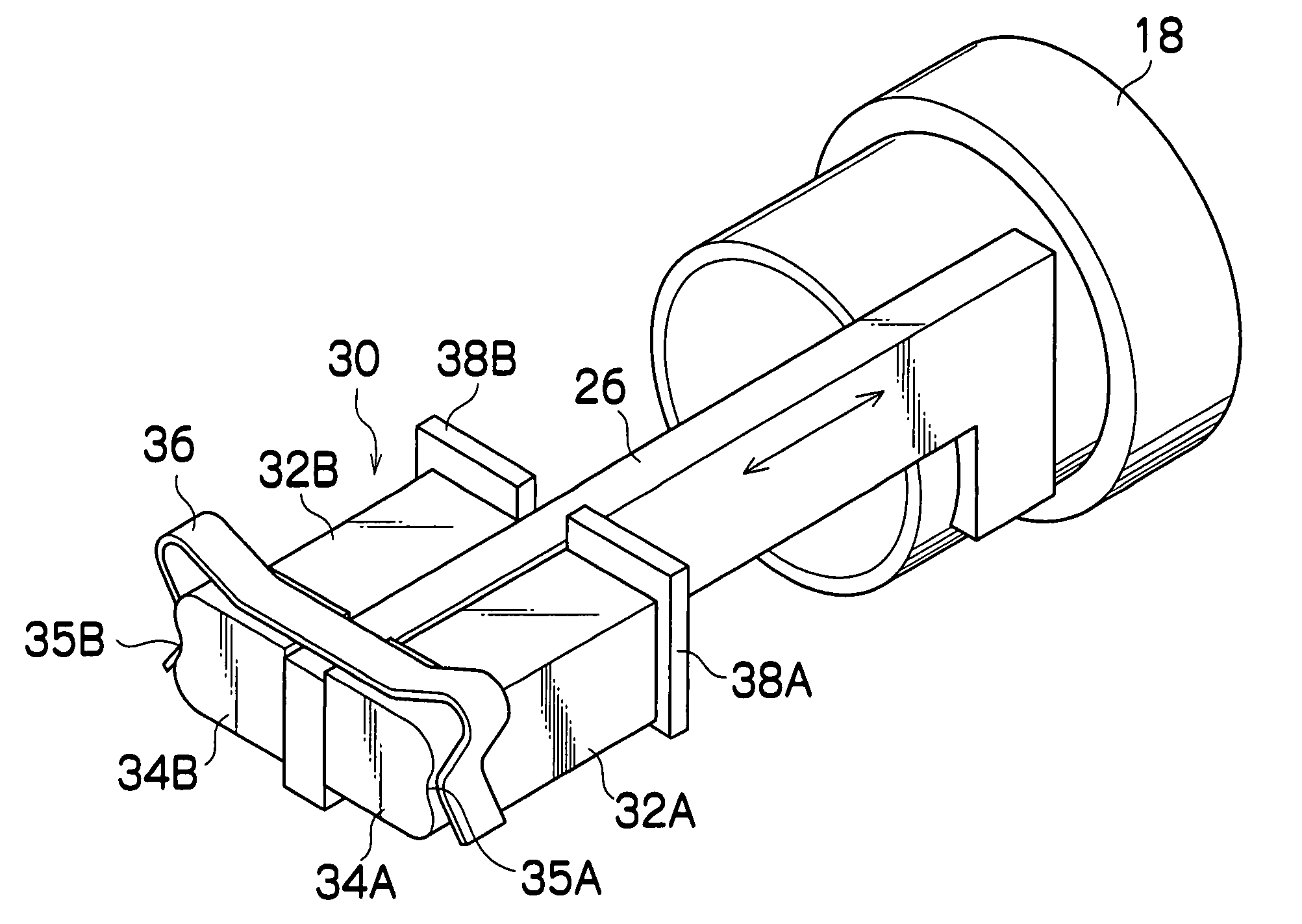
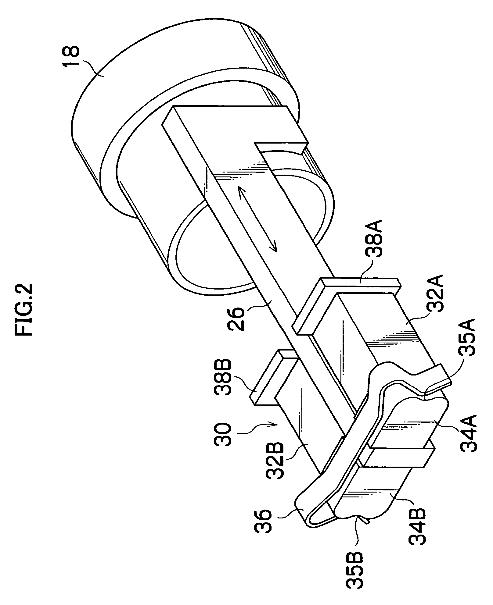
[0099] A comparative example in which voltage is applied to the piezoelectric elements 32A and 32B of the actuator 30 shown in FIGS. 1 and 2 in the substantially sawtooth shapes shown in FIG. 4A and FIG. 4B will be explained hereinafter.

[0100] In the case of FIG. 4A, the driving pulses in the same shape, namely, the substantially sawtooth-shaped driving pulses which gradually rise from the time β1 to the time β2, and abruptly falls at the time β3 are applied to the piezoelectric elements 32A and 32B. Accordingly, at the time β3, the piezoelectric elements 32A and 32B abruptly contract in the same timing.

[0101] Likewise, in the case of FIG. 4B, the driving pulses in the same shape, namely, the substantially sawtooth-shaped driving pulses which gradually fall from the time β4 to the time β5, and abruptly rise at the time β6 are applied to the piezoelectric elements 32A and 323B. Accordingly, at the ...

third embodiment

[0110] Next, an actuator of a third embodiment will be explained.

[0111]FIG. 11 is a perspective view showing a construction of a lens device to which the actuator of the third embodiment is applied. The lens device shown in the drawing has a box-shaped case 112, and a lens frame 118 which holds a movable lens (for example, a zoom lens and a focus lens) 116 is provided inside this case 112.

[0112] An engaging part 122 and a guide part 124 are formed to project on an outer peripheral surface of the lens frame 118. A U-shaped groove 123 is formed in the engaging part 122 and a guide rod 128 is engaged in this groove 123. A through-hole 125 is formed in the guide part 124, and a guide rod 129 is inserted through the through-hole 125. The guide rods 128 and 129 are placed in the optical axis direction, and are fixed to the case 112. Thereby, the lens frame 118 is supported slidably in the optical axis direction.

[0113] A driven member 126 is integrally mounted to the lens frame 118. The ...


PUM


Abstract

An actuator which drives a lens frame in an optical axis direction is constructed by piezoelectric elements, driving members, and a pressing spring. The piezoelectric elements are placed at opposite sides with a driven plate therebetween, and the driving members are fixed to the respective piezoelectric elements. The driving members are pressed against the driven plate from both sides by the pressing spring.

Description

BACKGROUND OF THE INVENTION [0001] 1. Field of the Invention [0002] The present invention relates to an actuator and its control method, and a lens device, and particularly relates to an actuator which is loaded on a compact precision apparatus such as a digital camera and a cellular phone to drive a zoom lens and a focus lens. [0003] 2. Related Art [0004] There is an actuator using a piezoelectric element as a drive device of a lens part of a digital camera or the like. For example, in an actuator in Japanese Patent No. 2633066, a driving rod is fixed to an end surface of the piezoelectric element and a lens-barrel is slidably supported at the driving rod. A plate spring is mounted to the lens-barrel so that the frictional force works between the lens-barrel and the driving rod by the elastic force of the plate spring. A driving pulse in a substantially sawtooth-shaped waveform is applied to the piezoelectric element, and the piezoelectric element deforms at different speeds in an ...

Claims


Application Information

Patent Timeline
Patent Type & Authority Applications(United States)
IPC IPC(8): G02B7/08G02B7/10H01L41/09H02N2/00
CPCG02B7/10H02N2/025H02N2/067
Inventor MANABE, MITSUOSASAKI, RYOTAMASUZAWA, TOMONARIEZAWA, TOSHIAKI
Owner FUJI PHOTO OPTICAL CO LTD
Why Eureka
Try Eureka