Eyeglass interface device and security system

a technology of eyeglasses and interface devices, which is applied in the field of eyeglass interface devices and security systems, can solve the problems of long high weight of the device itself, and discomfort of users wearing this eyewear, so as to reduce the time required to recognize one portion, the effect of reducing the time required for overall processing and reducing the time required for one portion

Inactive Publication Date: 2005-12-15
MURATA MFG CO LTD
View PDF4 Cites 114 Cited by
  • Summary
  • Abstract
  • Description
  • Claims
  • Application Information

AI Technical Summary

Benefits of technology

[0008] The present invention is directed to solving the above-described problems. Specifically, the present invention is directed to an eyeglass interface device and a security system that are lightweight and easy to use.

Problems solved by technology

The operation of this type of security system, therefore, takes a long time before the person enters / exits the gate.
Because the above-described previous art eyeglass interface device is configured to incorporate a high speed computer for processing the image of the retina and the like which is photographed by the camera into the temple of the eyewear or the like, however, the weight of the device itself is high, which may cause discomfort to a user wearing this eyewear.
Additionally, the power supply to the computer and the like is constituted by a battery incorporated in the temple tip section or the like, resulting in the time duration of operation of the computer being short, and thereby requiring frequent recharges or battery replacements, resulting in very poor usability.

Method used


Image

  • Eyeglass interface device and security system
  • Eyeglass interface device and security system
  • Eyeglass interface device and security system

Examples


first embodiment

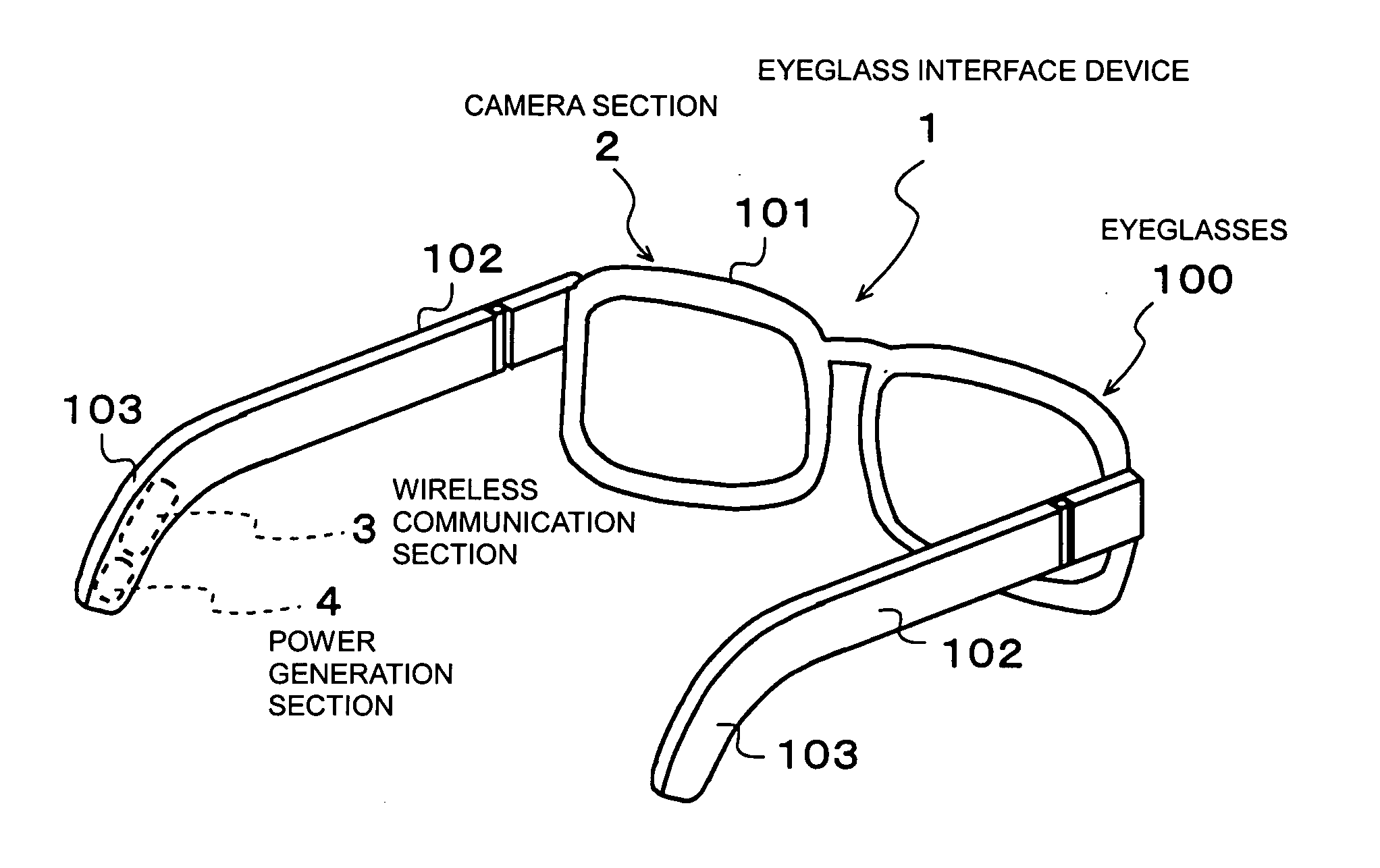
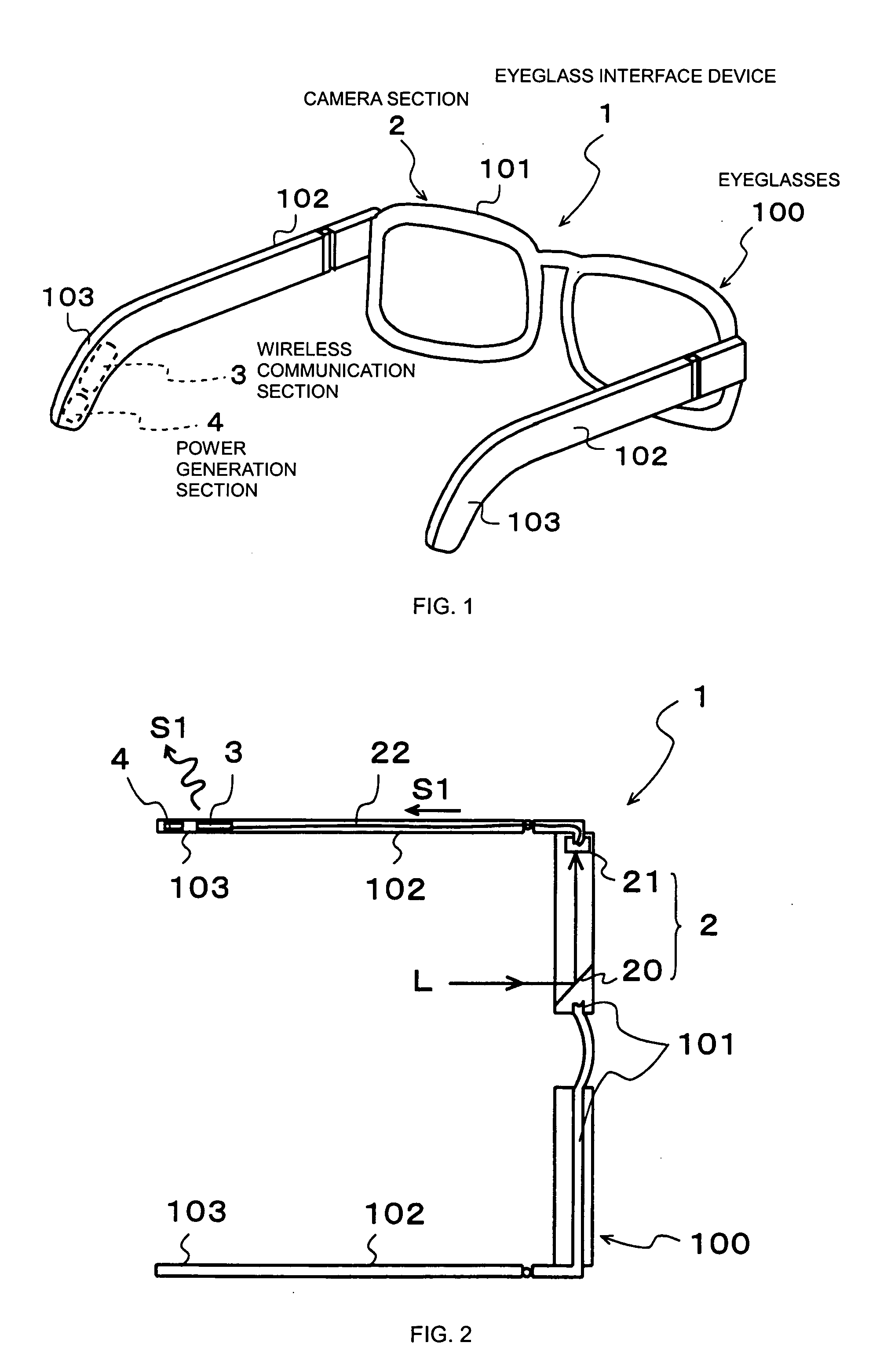
[0036]FIG. 1 is a perspective view of an eyeglass interface device according to a first embodiment of the present invention.

[0037] This eyeglass interface device 1 is configured to integrate interface elements within eyeglasses 100. Here, the interface elements comprise a camera section 2, a wireless communication section 3, and a power generation section 4.

[0038] The camera section 2 is a section for picking up, acquiring, the image of the retina constituting a portion of the user's eyeball, and outputting an imaging signal thereof to the wireless communication section 3.

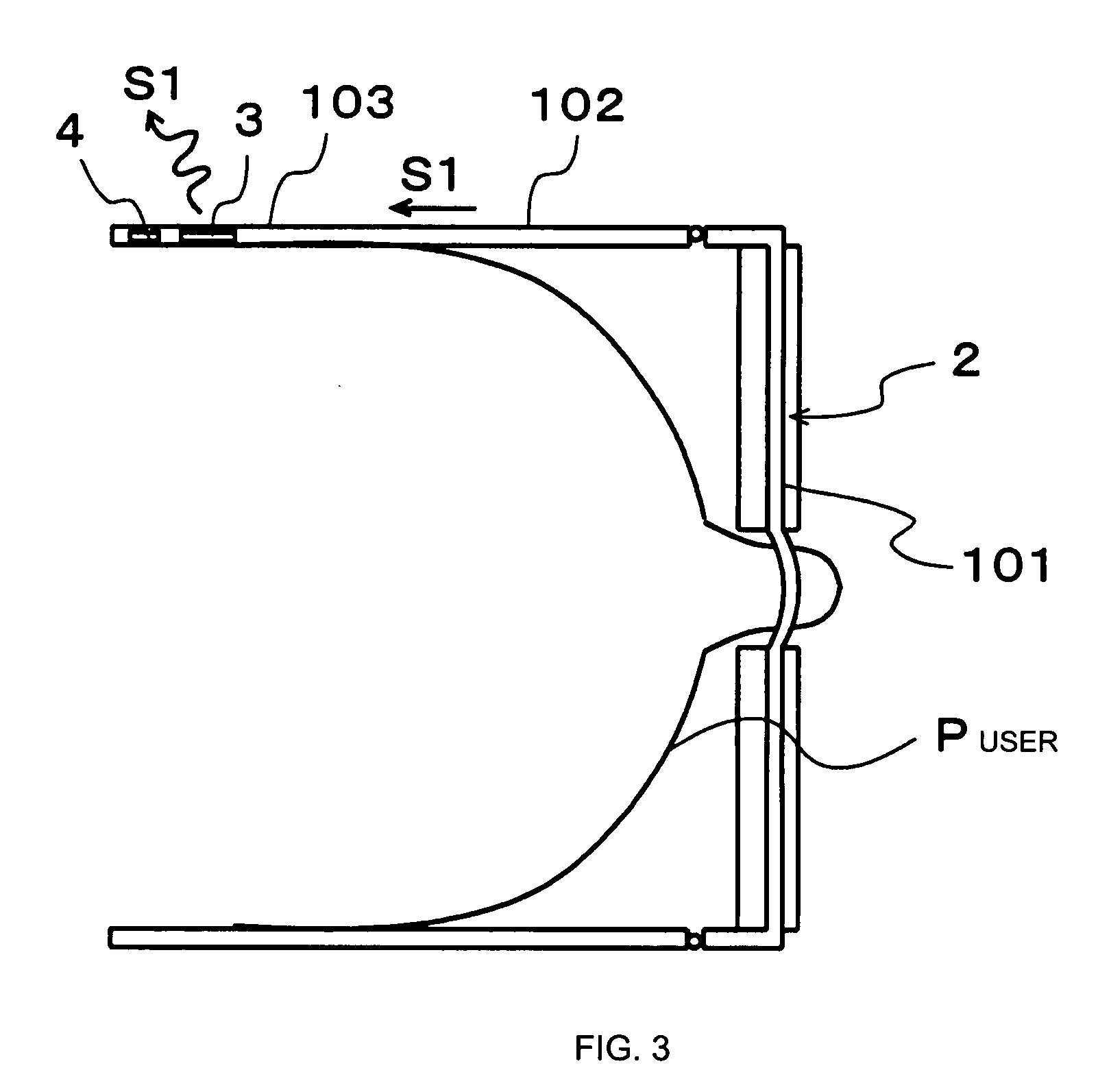
[0039]FIG. 2 is a schematic plan view showing the structure of the camera section 2. As shown in FIG. 2, the camera section 2 is constituted of a mirror 20 and a sensor 21. The mirror 20, with its reflection surface tilted at a predetermined angle toward the user's eyeball (the left side in FIG. 2), is mounted to the inside of the lens frame 101 of the eyeglasses 100. On the other hand, the sensor 21 is formed o...

second embodiment

[0048] Next, a second embodiment of the present invention will be described.

[0049]FIG. 4 is a plan view of the main portion of the eyeglass interface device 1 according to the second embodiment of the present invention. As shown in FIG. 4, the eyeglass interface device 1 according to the second embodiment is different from the above-described first embodiment in that it has a display section 5.

[0050] Specifically, the eyeglass interface device 1 has a display section 5 provided to each of a pair of lenses 104 of the eyeglasses 100. More specifically, a projection section 50 is provided on each of the temples 102. Also, a mirror 51 with its reflection surface tilted toward the projection section 50 side is provided to each of the lenses 104, as well as a beam splitter 52 is provided to each of the lenses 104 so as to face a respective one of the mirrors 51.

[0051] Each of the two projection sections 50 is connected to the wireless communication section 3 through a line 53, whereby ...

third embodiment

[0054] A third embodiment of the present invention will now be described.

[0055]FIG. 5 is a plan view of the main portion of the eyeglass interface device 1 according to the third embodiment of the present invention. As shown in FIG. 5, the eyeglass interface device 1 according to the third embodiment is different from the above-described first and second embodiments in that it has an audio section 6.

[0056] According to FIG. 5, the audio section 6 is disposed within one of the temple tip portions 103 of the eyeglasses 100. The audio section 6 constitutes of a bone conduction earphone 60 and a microphone 61, and is connected to the wireless communication section 3 via a line 62 passed through one temple 102, the lens frame 101, and the other temple 102.

[0057] Thereby, it is possible to transmit / receive audio information such as sound through the wireless communication section 3. Specifically, audio information sent from external equipment such as a mobile phone or the like to the w...


PUM


Abstract

An eyeglass interface device includes a camera section, a wireless communication section, and a power generation section. The camera section acquires the image of the retina of an eyeball of a user, and outputs the imaging signal thereof to the wireless communication section. The wireless communication section transmits the imaging signal from the camera section by a radio wave. The power generation section supplies power to the camera section and the wireless communication section. The eyeglass interface device preferably includes a display section for displaying, on eyeglass lenses, image information sent from a mobile phone or the like to the wireless communication section, and an audio section having a bone conduction earphone and a microphone.

Description

BACKGROUND OF THE INVENTION [0001] 1. Field of the Invention [0002] The present invention relates to an eyeglass interface device that integrates interface elements within an eyewear, and a security system that recognizes the identity of a human using this eyeglass interface device. [0003] 2. Description of the Related Art [0004] Recently, security systems are becoming widespread that detect the retina of a person who is attempting to enter / exit the gate of a building, to thereby determine whether the person may proceed in accordance with the retina information. [0005] However, this type of security system is one in which the person attempting to enter / exit the gate presents their eye to a camera provided at the entrance / exit of a building or the like, and after the camera has photographed the retina of the eye, a separate processing device determines the identity between this retina information and retina information that has been registered, to thereby open / close the entrance / exit...

Claims


Application Information

Patent Timeline
Patent Type & Authority Applications(United States)
IPC IPC(8): A61B3/12A61B3/14A61B5/117G02B27/00G02B27/01G02B27/02G02C11/00G02C11/06G02C13/00G06K9/00G07C9/00H04M11/00H04N7/14
CPCA61B3/12A61B3/145A61B5/117G02B27/017G02C11/10G02B2027/0187G02C11/06G06K9/00597G07C9/00158G02B2027/0138G07C9/37G06V40/18A61B5/1171
Inventor ISHIKAWA, YOHEINISHIZAWA, HIDEOGOTO, MASAFUMI
Owner MURATA MFG CO LTD
Why Eureka
Try Eureka