Self-leveling camera head

a camera head and self-leveling technology, applied in the field of optical viewing systems, can solve the problems of not being able to manually correct, the video image can be tedious and annoying, and the camera head moves along the pipe at a regular interval

Active Publication Date: 2005-12-15
SEEK TECH
View PDF3 Cites 112 Cited by
  • Summary
  • Abstract
  • Description
  • Claims
  • Application Information

AI Technical Summary

Benefits of technology

[0011] In accordance with one aspect of the present invention a self-leveling camera head includes an outer housing and a camera module assembly including an image sensor supported inside the outer housing for free rotation around a first axis. A leveling weight assembly is supported inside the outer housing separate from the camera module assembly for free rotation about a second axis, which preferably substantially conincides with the first axis, as a result of a center of gravity of the leveling weight assembly being displaced from the second axis. The leveling weight assembly is removably coupled to the camera module assembly so that the leveling weight assembly can turn the camera module assembly to a predetermined angular orientation.

Problems solved by technology

However, since the camera head is inaccessible after it has been pushed down the pipe, it cannot be manually righted.
In some cases, water may be present in the bottom of the pipe, in which case the viewer has a frame of reference, but even then, the periodic twisting of the video image as the camera head moves along the pipe can be very tedious and annoying.
Furthermore, water is not always present, or it may fill the pipe entirely.
This design is not compact and rugged enough for use by plumbers.
The Pearpoint camera head is complex, expensive to manufacture and subject to failures since it lacks the ruggedness required in many pipe inspection applications.
The motorized mechanisms take up substantial space inside the camera head, thereby making it difficult to downsize the camera head for inspecting small pipes.
However, this design does not lend itself to easy removal and / or repair of the video camera and associated electronics within the camera head.
Pipe inspection systems in use today that invert the image on the monitor do not allow the inverted image to be recorded.
The primary disadvantage is the limited rotational resolution (only offering two positions—0 degrees and 180 degrees of rotation).
This approach is optimal in terms of the rotational resolution, however it is extremely computationally intense, and therefore requires a significant cost in parts and power.
It also suffers from the drawback that the rectangular 4:3 array is clipped so that some video content is lost at any angles other than zero and one hundred and eighty degrees.

Method used


Image

  • Self-leveling camera head
  • Self-leveling camera head
  • Self-leveling camera head

Examples


Embodiment Construction

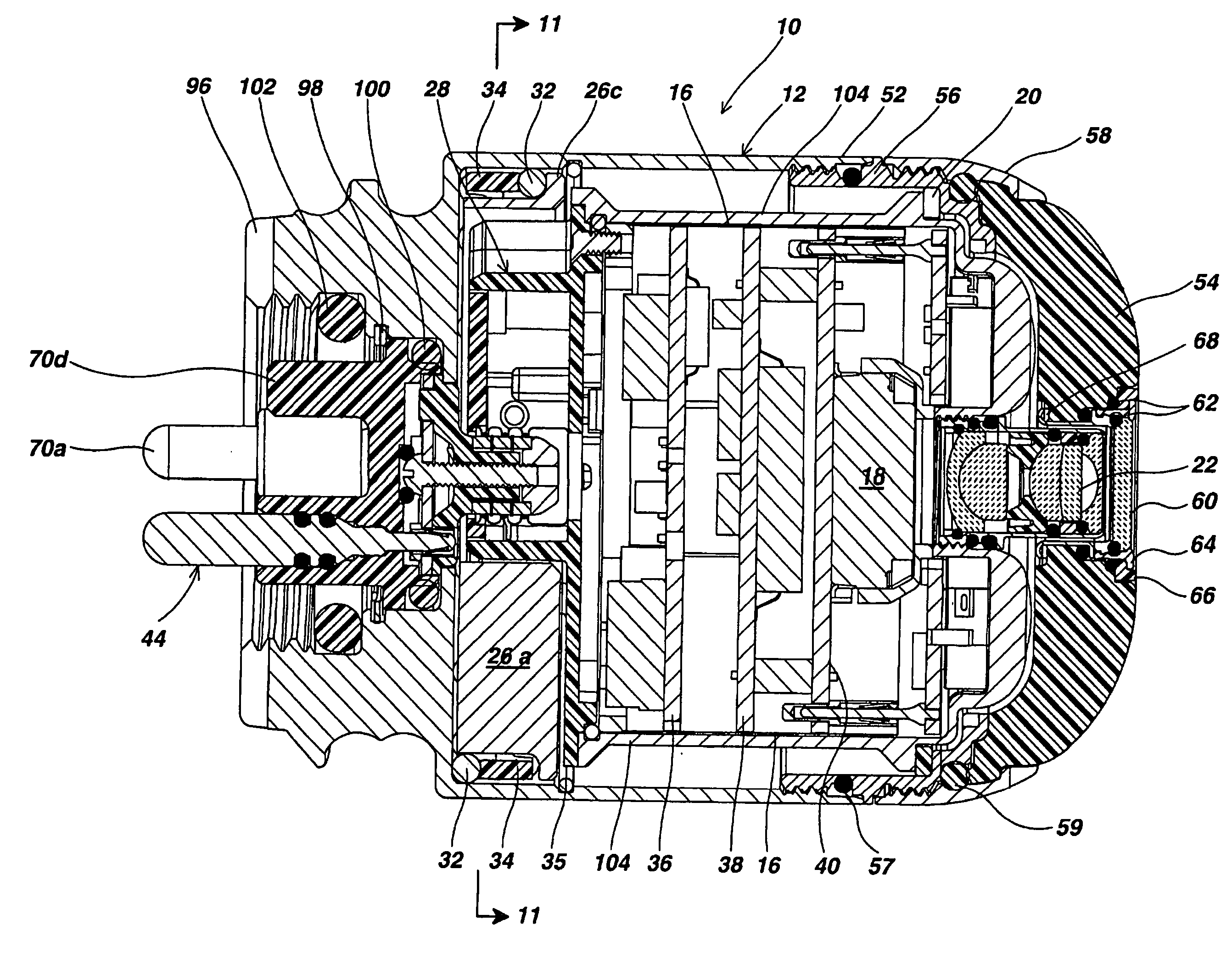
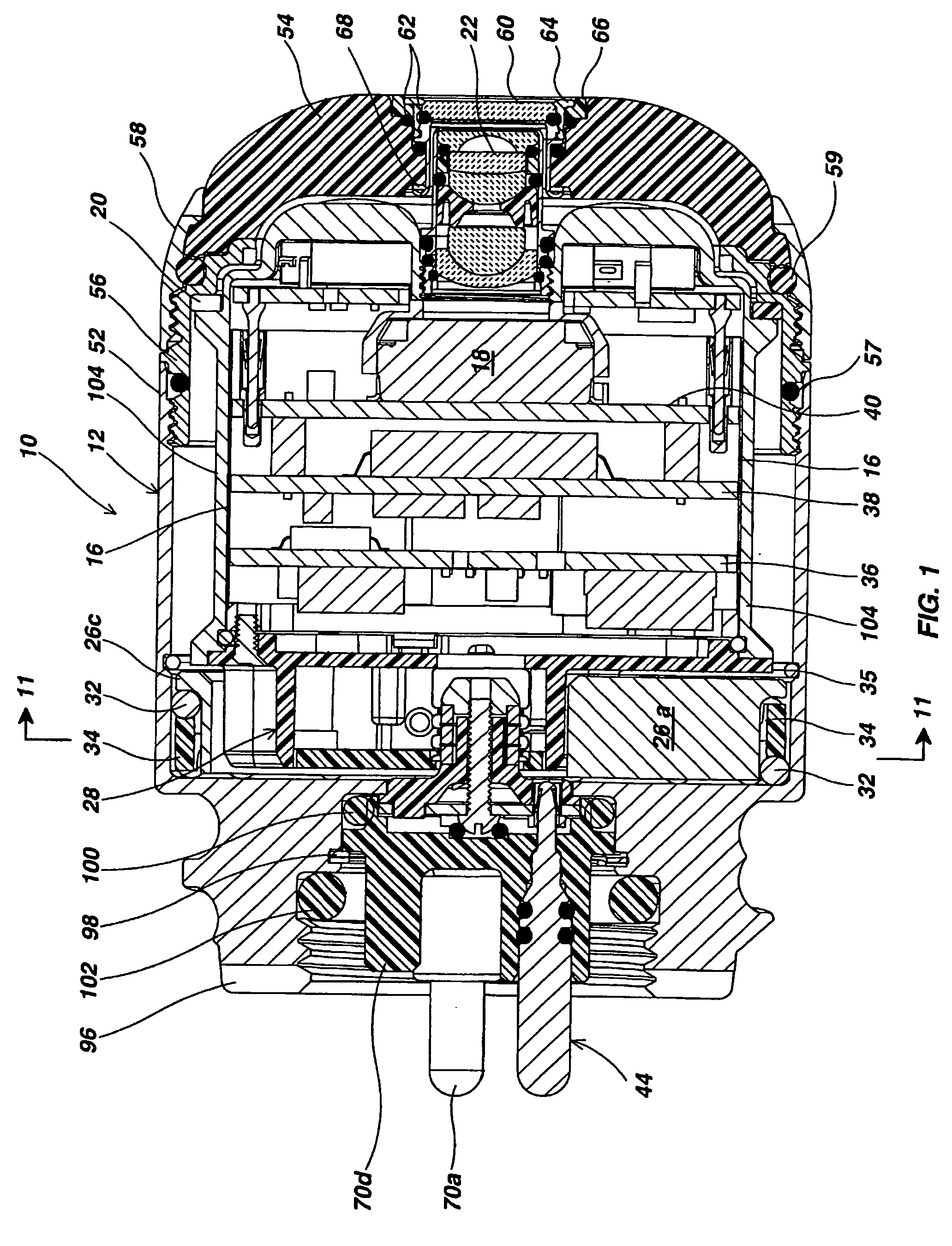
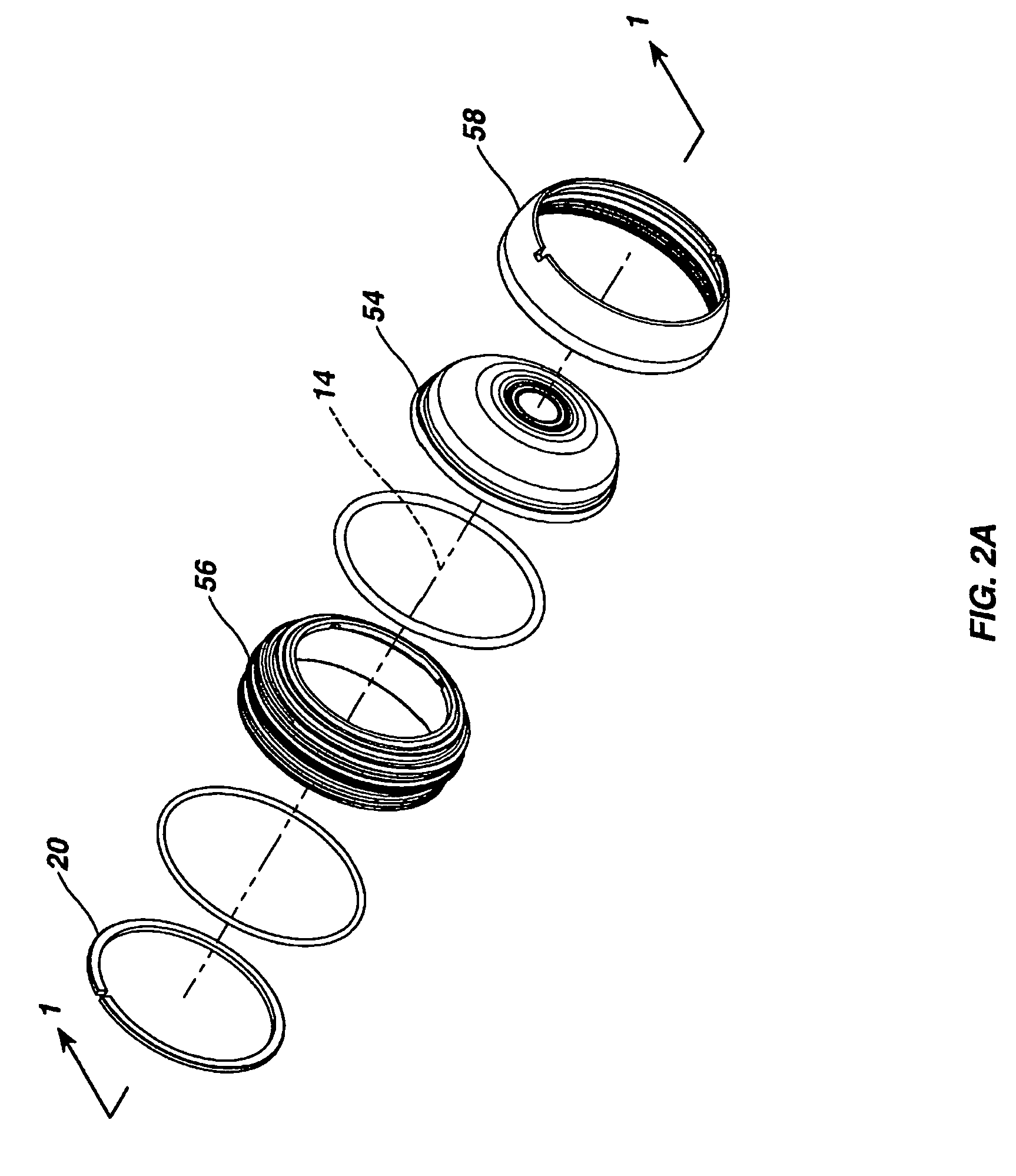
[0031] Referring to FIG. 1, a self-leveling camera head 10 includes a stainless steel generally cylindrical outer housing 12 having a central axis 14 (FIGS. 2A, 2B and 2C). A camera module assembly 16 (FIG. 2B) including an image sensor 18 is supported inside the outer housing 12 for free rotation around the central axis 14 via Teflon (trademark) or Teflon composite split-ring bushing 20. Other forms of low friction material may be used to fabricate the bushing 20. The image sensor 18 is preferably a charge coupled device (CCD) and has associated filter elements for producing output signals that represent a color image based on light reflected from scenes and objects within a field of view established by a lens assembly 22 illuminated by an LED assembly 24 (FIG. 2B). The image sensor 18 could also be a CMOS imager.

[0032] The lens assembly 22 (FIGS. 1 and 2B) focuses light on the image sensor 18. It is mounted in a threaded assembly so that it can be screwed back and forth along the...


PUM


Abstract

A self-leveling camera head includes an eccentric leveling weight assembly that is supported inside an outer housing for free rotation about an axis. The leveling weight assembly can be removably coupled to a separate camera module assembly supported inside the outer housing for rotation about the axis so that its images will be “upright”, i.e. earth normal. A slip ring assembly includes a fixedly mounted connector assembly that removably mates with a contact assembly mounted to the camera module assembly. In an alternative embodiment the camera module assembly does not rotate within the outer housing. Instead a processing circuit processes a video output from a high resolution image sensing device in the camera module assembly, generates a sub-sampled region and rotates it into a predetermined orientation for display. The output of an orientation sensor in the camera head may be processed to achieve the predetermined desired orientation of the video that is stored or displayed.

Description

FIELD OF THE INVENTION [0001] The present invention relates to optical viewing systems, and more particular, to video pipe inspection systems. BACKGROUND OF THE INVENTION [0002] There are many applications where a video camera may be used, where the target being observed is not oriented such that it is “upright”, i.e. earth normal, in the video scene that is being presented on a monitoring or recording device. Such is often the case in video inspection systems, where a camera is used to look inside of an opening, and the camera may rotate during its traversal towards the observation point. It is also the case where a fixed orientation camera is used to observe variable orientation objects—such as a camera observing a manufacturing process that produces items with variable orientation (such as text printed on bottle caps, which are affixed to bottles, and are being monitored as they roll by). It is further often desirable to orient the video so that it more closely approximates “upri...

Claims


Application Information

Patent Timeline
Patent Type & Authority Applications(United States)
IPC IPC(8): H04N5/225H04N5/232
CPCG03B37/005H04N5/2252H04N5/2259H04N5/2254H04N2005/2255G01N21/8803H04N5/23293H04N23/555H04N23/58H04N23/55H04N23/51H04N23/63H04N23/54H04N23/56H04N23/57G01N21/954
Inventor OLSSON, MARK S.LOBREE, BRET D.COX, DAVID A.
Owner SEEK TECH
Why Eureka
Try Eureka