
Fiber optic transceiver module with rigid and flexible circuit boards

a technology of fiber optic transceiver module and circuit board, applied in the direction of optical waveguide light guide, optical element, instrument, etc., can solve the problems of board reliability problems, high cost of the concept illustrated at fig. 9 and other problems

Active Publication Date: 2005-12-15
SUMITOMO ELECTRIC DEVICE INNOVATIONS U S A
View PDF4 Cites 68 Cited by
  • Summary
  • Abstract
  • Description
  • Claims
  • Application Information

AI Technical Summary

Problems solved by technology

This concept illustrated at FIG. 9 is understandably expensive due to the difficulty in making the board, i.e., it tends to have undesirably long fab cycles.
Moreover, the resulting boards are also prone to have reliability issues.

Method used


Image

  • Fiber optic transceiver module with rigid and flexible circuit boards
  • Fiber optic transceiver module with rigid and flexible circuit boards
  • Fiber optic transceiver module with rigid and flexible circuit boards

Examples


Embodiment Construction

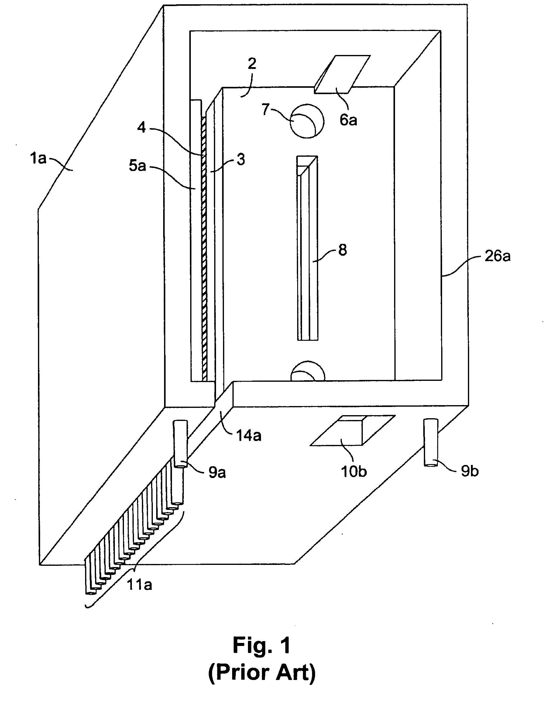
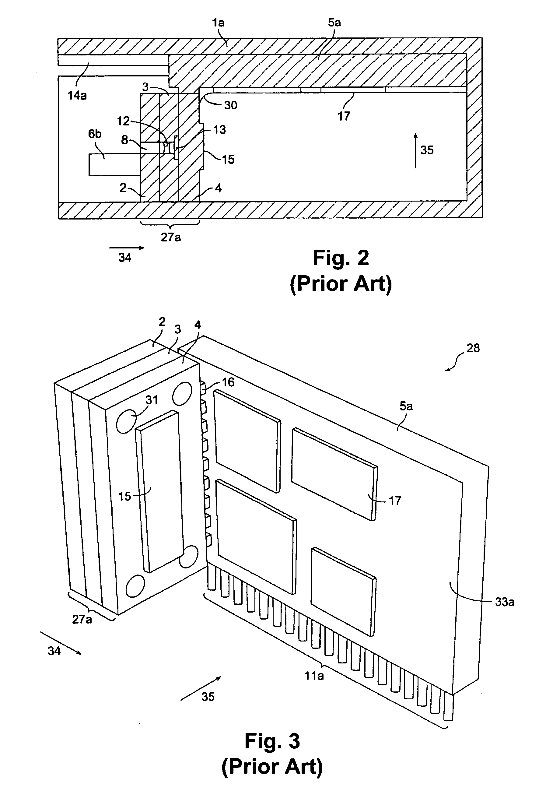
[0030] One or more preferred embodiments of the invention will now be described in detail with reference to the Figures. Assembly configurations 1a, 1b or housings 1a, 1b (see FIGS. 1 and 4) are first described in accordance with preferred embodiments with reference to FIGS. 1-8. A housing such as one of these exemplary housings 1a, 1b preferably contain the optical transceiver of the invention and / or in combination the optical transceiver and housing comprise the invention. An optical transceiver in accordance with a preferred embodiment is particularly described with reference to FIGS. 10-13.

[0031]FIG. 1 shows a perspective view of a first assembly configuration with a first subassembly 27a (see FIGS. 2 and 3) being connected to the first transceiver board 5a along a perpendicular direction. The first subassembly 27a comprises typically the adapter module 2, the lens module 3 and the duplex transceiver module 4. The adapter module 2 has precision alignment features 7 that are pre...


PUM


Abstract

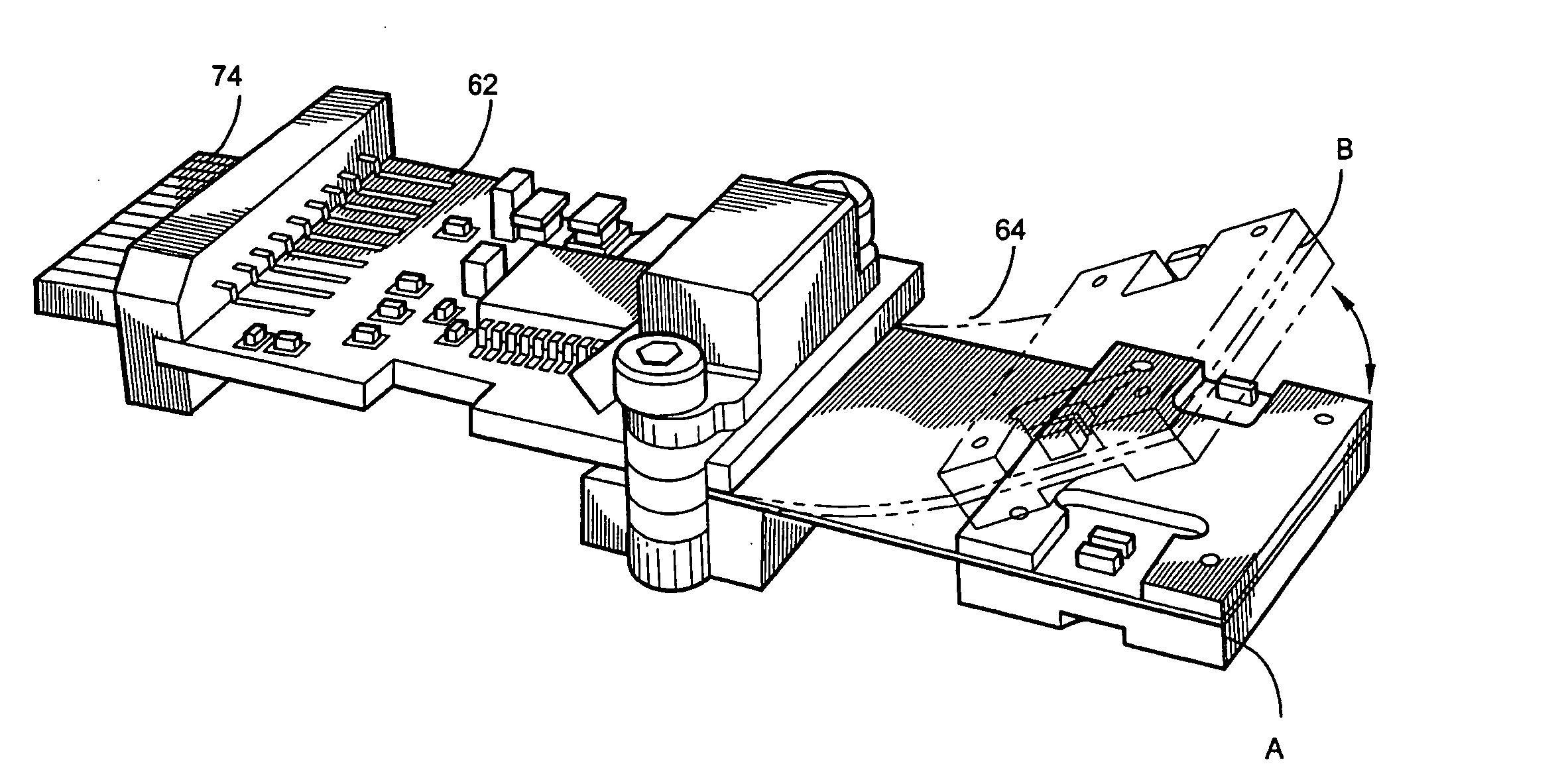
An optical transceiver for converting and coupling an information-containing electrical signal with an optical fiber includes a housing and coupled rigid and flex printed circuit boards. The housing includes a fiber optic connector adapted for coupling with an external optical fiber for transmitting and / or receiving an optical communications signal. The rigid printed circuit board is within the housing and includes an electrical connector for coupling with an external electrical cable or information system device, and for transmitting and / or receiving an information-containing electrical communications signal. A first interface connector is for receiving or transferring the electrical signal. A flexible printed circuit board is also within the housing and coupled to the rigid printed circuit board, including a second interface connector for mating with the first interface connector, and transmitting or receiving the electrical signal to or from the rigid printed circuit board. An electro-optical subassembly on the flex board is for converting between an electrical signal and a modulated optical signal. The flex board is adapted for coupling to the fiber optic connector.

Description

BACKGROUND [0001] 1. Field of the Invention [0002] The invention relates to electro-optic conversion modules, and particularly to connecting rigid and flex circuit boards in parallel optical media converters. [0003] 2. Description of the Related Art [0004] The speed of computers and the data transfer between them is ever increasing. Optical data transmission techniques have been developed to provide high capacity signal transmission without many of the physical limitations for electrical cables. Fiber-optic cables have advantageous transmission characteristics, which are utilized with optoelectronic devices such as fiber-optic transceivers by converting electrical signals into optical signals and vice versa at the ends of the fiber-optic cables. [0005] The typical hardware architecture of computers involves circuit boards that are perpendicularly connected with a pin edge or a pin array in lengthy multi-pin connectors, which are laterally arrayed on a mother board. That way, the cir...

Claims


Application Information

Patent Timeline
Patent Type & Authority Applications(United States)
IPC IPC(8): G02B6/36G02B6/42H05K1/14
CPCG02B6/4201H05K1/147G02B6/4246G02B6/428G02B6/4283G02B6/4281
Inventor WANG, CHARLES XIAOZHONGLAU, EDMOND
Owner SUMITOMO ELECTRIC DEVICE INNOVATIONS U S A
Learn More