Reciprocating fluid pump assembly employing reversing polarity motor

a reciprocating pump and motor technology, applied in the direction of positive displacement liquid engines, piston pumps, liquid fuel engines, etc., can solve the problems of adverse effects, increased current levels required for such forces, and extremely rapid cycle times, so as to reduce cycle times and control the initial position

Inactive Publication Date: 2005-12-15
BRP US
View PDF46 Cites 47 Cited by
  • Summary
  • Abstract
  • Description
  • Claims
  • Application Information

AI Technical Summary

Benefits of technology

[0009] The present invention provides a novel technique for pumping fluids in a reciprocating pump arrangement designed to respond to these needs. The technique is particularly well suited for use in fuel delivery systems, such as in direct, in chamber fuel injection. However, the technique is in no way limited to such applications, and may be employed in a wide range of technical fields. The pumping drive system offers significant advantages over known arrangements, including a reduction in cycle times, controllability of initial positions of a reciprocating assembly, controllability of stroke of a reciprocating assembly, and thereby of displacement per cycle, and so forth.

Problems solved by technology

Where such pumps are employed in demanding applications, such as for supplying fuel to combustion chambers of an internal combustion engine, cycle times can be extremely rapid.
While the cycle time may be reduced by providing stronger springs for returning the reciprocating assembly to the initial position, such springs have the adverse effect of opposing forces exerted on the reciprocating assembly by energization of the solenoid.
At some point, however, increased current levels required for such forces become undesirable due to the limits of the electrical components, and additional heating produced by electrical losses.

Method used


Image

  • Reciprocating fluid pump assembly employing reversing polarity motor
  • Reciprocating fluid pump assembly employing reversing polarity motor
  • Reciprocating fluid pump assembly employing reversing polarity motor

Examples


Embodiment Construction

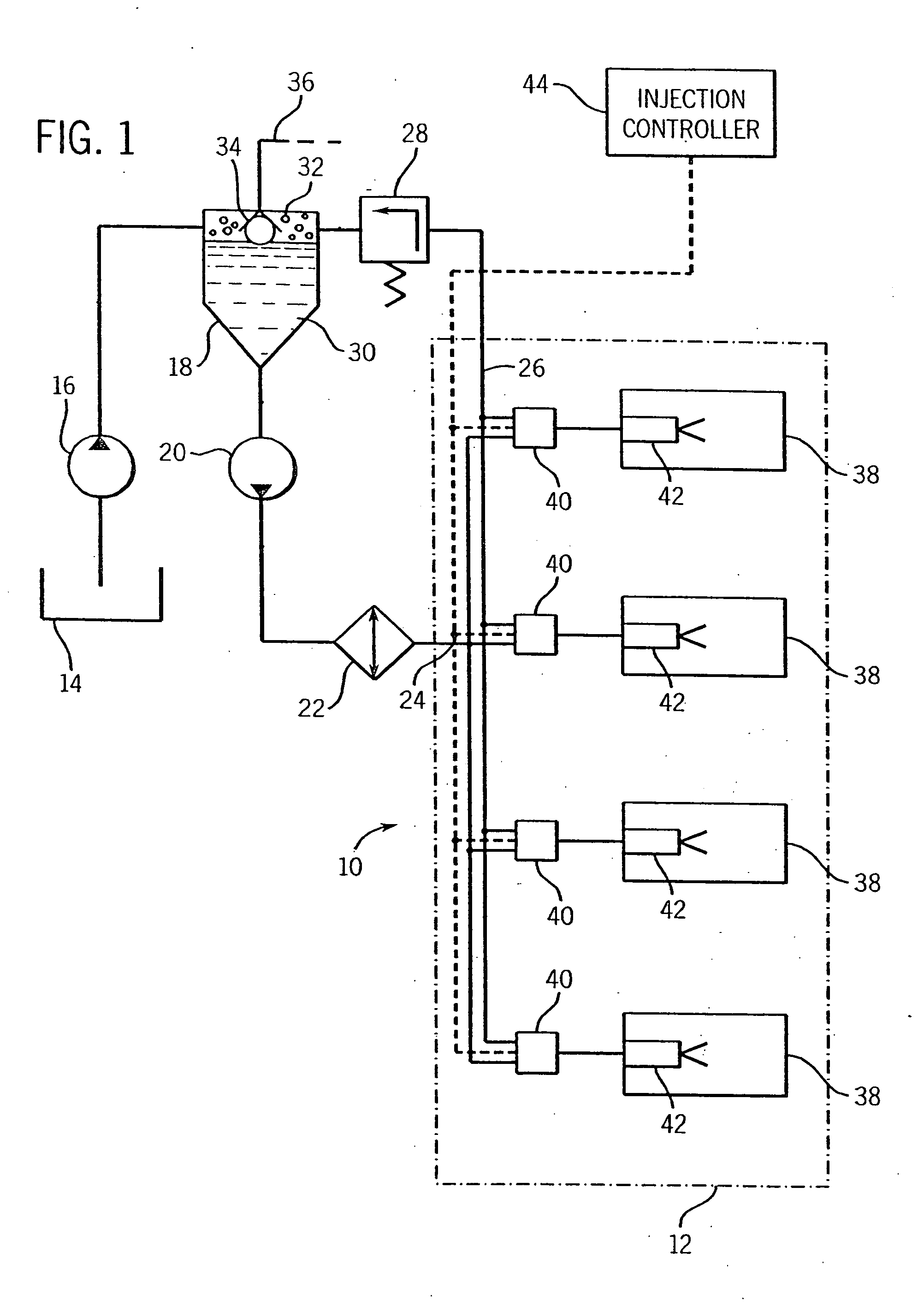
[0017] Turning now to the drawings and referring first to FIG. 1, a fuel injection system 10 is illustrated diagrammatically, including a series of pumps for displacing fuel under pressure in an internal combustion engine 12. While the fluid pumps of the present technique may be employed in a wide variety of settings, they are particularly well suited to fuel injection systems in which relatively small quantities of fuel are pressurized cyclically to inject the fuel into combustion chambers of an engine as a function of the engine demands. The pumps may be employed with individual combustion chambers as in the illustrated embodiment, or may be associated in various ways to pressurize quantities of fuel, as in a fuel rail, feed manifold, and so forth. Even more generally, the present pumping technique may be employed in settings other than fuel injection, such as for displacing fluids under pressure in response to electrical control signals used to energize coils of a drive assembly,...


PUM


Abstract

A reciprocating pump includes a drive section and a pump section. The drive section has a reciprocating coil assembly to which alternating polarity control signals are applied during operation. A permanent magnet structure of the drive section creates a magnetic flux field which interacts with an electromagnetic field produced during application of the control signals to the coil. Depending upon the polarity of the control signals applied to the coil, the coil is driven in one of two directions of movement. A drive member transfers movement of the coil to a pump element which reciprocates with the coil to draw fluid into a pump chamber and expel the fluid during each pump cycle. The pump is particularly well suited to cyclic pumping applications, such as fuel injection systems for internal combustion engines.

Description

[0001] This application claims priority from U.S. is a continuation of U.S. application Ser. No. 09 / 528,766 filed Mar. 17, 2000, which is incorporated herein by reference.BACKGROUND OF THE INVENTION [0002] 1. Field of the Invention [0003] The present invention relates generally to the field of electrically-driven reciprocating pumps. More particularly, the invention relates to a pump which is particularly well suited for use as a fuel pump, driven by a solenoid assembly employing a permanent magnet and a solenoid coil to produce pressure variations in a pump section and thereby to draw into and express from the pump section a fluid, such as a fuel being pumped. The invention also relates to a fuel injector assembly employing such a pump. [0004] 2. Description of the Related Art [0005] A wide range of pumps have been developed for displacing fluids under pressure produced by electrical drives. For example, in certain fuel injection systems, fuel is displaced via a reciprocating pump ...

Claims


Application Information

Patent Timeline
Patent Type & Authority Applications(United States)
IPC IPC(8): F04B17/04
CPCF04B17/046F04B17/042
Inventor RADUE, MARTIN L.
Owner BRP US
Why Eureka
Try Eureka