Synthetic resin guide

a resin guide and resin technology, applied in the direction of belts/chains/gears, mechanical equipment, etc., can solve the problems of inadequate pressure exerted by the pressing head on the plate, and achieve the effect of reducing the requirement for guide molding accuracy, increasing dimensional tolerance, and stable operation

Inactive Publication Date: 2005-12-15
TSUBAKIMOTO CHAIN CO
View PDF13 Cites 26 Cited by
  • Summary
  • Abstract
  • Description
  • Claims
  • Application Information

AI Technical Summary

Benefits of technology

[0014] The holes for receiving a mounting member, in the guide body and the reinforcing plate, can be of different sizes. For example the diameter of the hole in the reinforcing plate can be larger than the diameter of the hole in the guide body so that the axes of the holes can be slightly misaligned without making it more difficult to fit the assembly to a mounting member such as a shoulder bolt projecting from an engine block. Additionally, by increasing dimensional tolerance in this manner, a reduced requirement for guide molding accuracy can be realized.
[0015] The reinforced guide is able to apply proper tension to a traveling power transmission medium and thereby achieve stable operation without side run-out or vibration either in, or transverse to, the plane of movement of the transmission medium.
[0016] Since the pressing member uniformly engages and presses against a positioning hole formed in the reinforcing plate, the synthetic resin guide body and the reinforcing plate can be easily assembled without the need for additional parts. Moreover, because the mounting holes of the guide body and the reinforcing plate are reliably positioned in coaxial relationship, the assembly can be easily mounted on a mounting member without the need to adjust the relationship between these holes.
[0017] Furthermore, since the diameter of the pressing head is larger than the diameter of the positioning hole, even if the pressing member is warped, the pressing head will uniformly press the reinforcing plate without biased contact with the positioning hole of the reinforcing plate. No gap is produced between the pressing head and the positioning hole of the reinforcing plate, and consequently, vibration noise due to such a gap is avoided.

Problems solved by technology

If the pressing head is spherical, especially if the height of the pressing head is the same as the height of the positioning hole, warping of the pressing member upon insertion of the reinforcing plate occurs, and the pressure exerted by the pressing head on the plate may become inadequate.

Method used


Image

  • Synthetic resin guide
  • Synthetic resin guide
  • Synthetic resin guide

Examples


Embodiment Construction

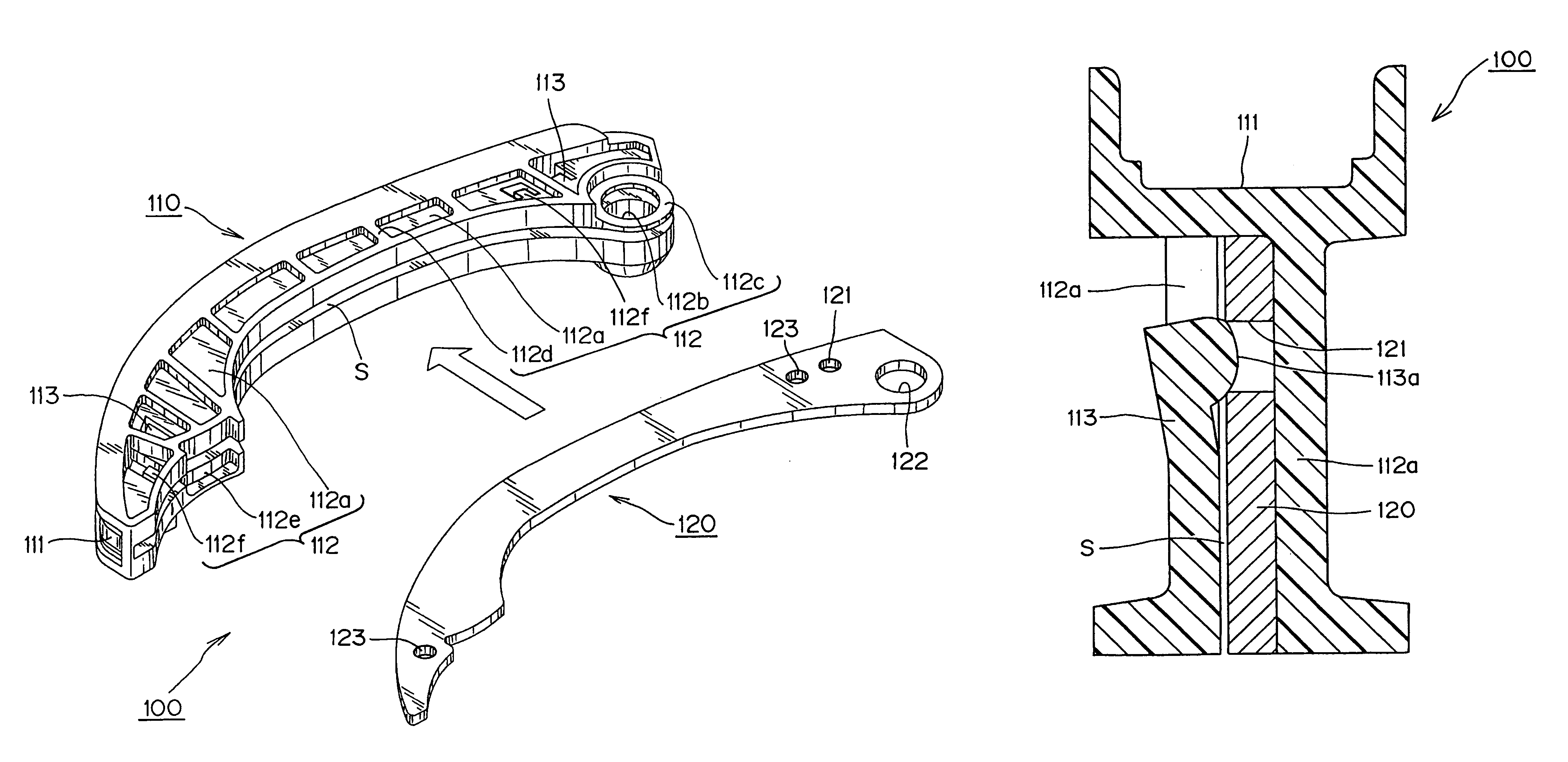
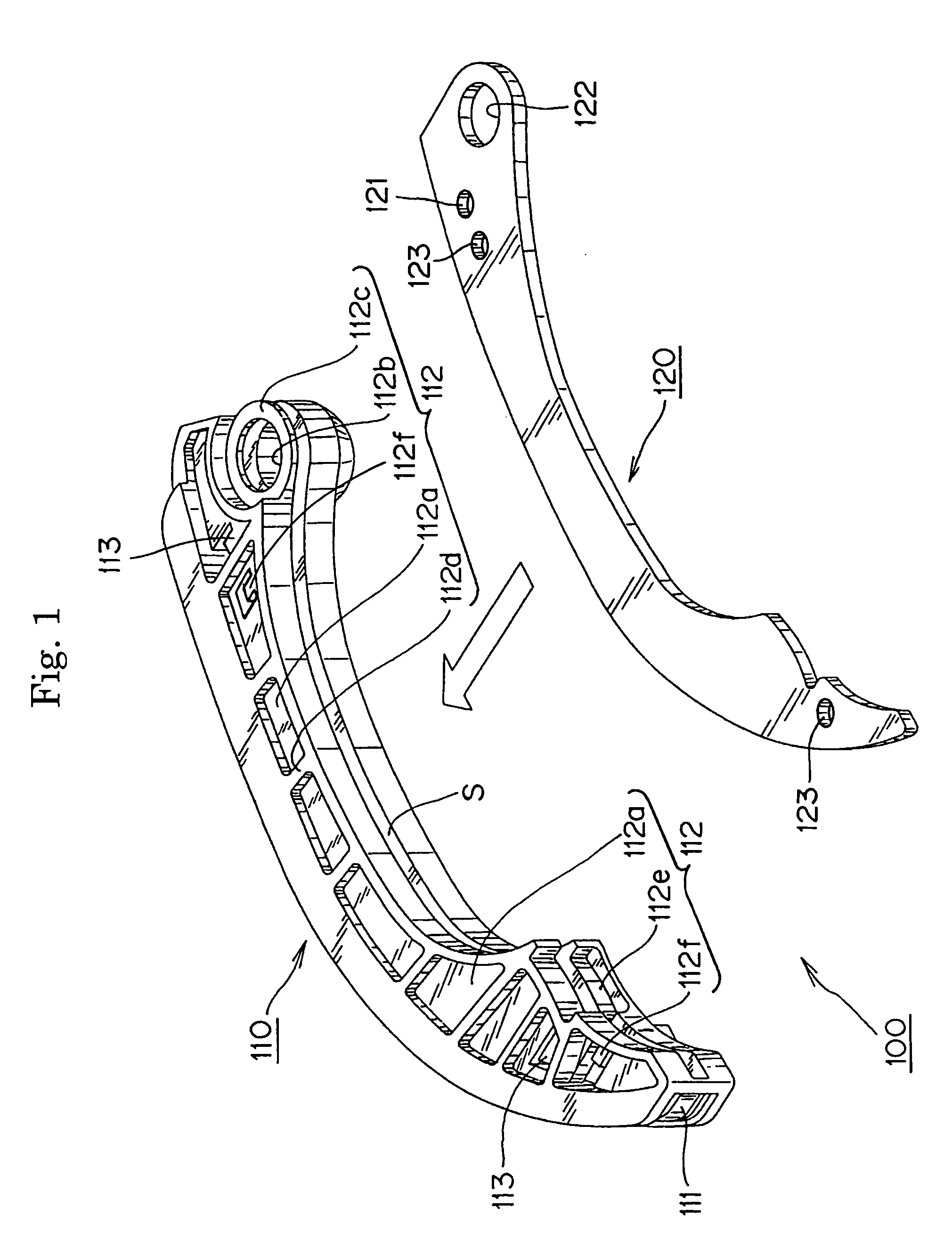
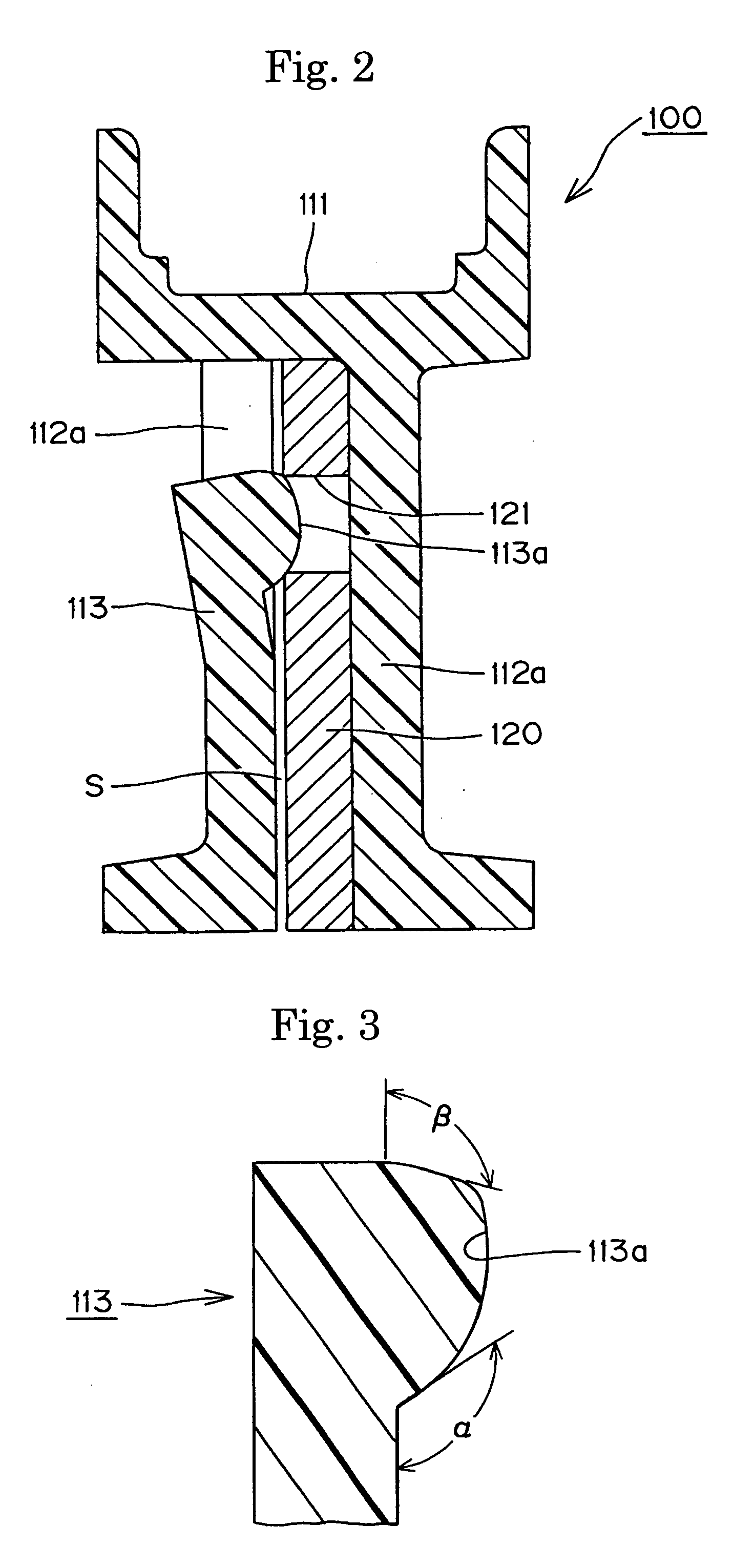
[0026] A synthetic resin guide 100, in accordance with the invention, is shown in FIGS. 1 and 2. This guide is designed to serve as a tensioner lever, controlling tension in a chain with which it is in sliding engagement by pivoting against the chain about a mounting member such as a shoulder bolt (not shown) extending from an engine block. The guide is preferably a two-part structure comprising an integrally molded, synthetic resin guide body 110, and a reinforcing plate 120, which is preferably punched from a steel sheet. The reinforcing plate 120 is inserted into the guide body 110 in the direction of the arrow shown in FIG. 1.

[0027] The guide body 110 is composed of a shoe 111, with a chain-engaging surface on a front side thereof, and extending along the longitudinal direction of the guide, for sliding contact with a chain, and a shoe support 112, on the back side of the shoe opposite from the side on which the chain-engaging surface is formed. The shoe support 112 includes a ...


PUM


Abstract

A synthetic resin guide for a transmission device comprises an integrally molded, synthetic resin guide body having a shoe with a front surface for sliding contact with a chain, and a support on its back surface, the support having a longitudinal slot, formed between two opposed walls, for receiving a reinforcing plate. Both the guide body and the plate having mounting holes that are coaxial when the plate is incorporated into the guide body. A pressing member, integrally formed on one of the walls of the guide body, includes an eccentric head which uniformly presses against opposite parts of the edge of an opening of a positioning hole in the reinforcing plate.

Description

FIELD OF THE INVENTION [0001] This invention relates to a synthetic resin guide for an endless, traveling, flexible, power transmission medium, such as a roller chain, a silent chain, or a toothed belt, used to transmit rotation from a driving sprocket to one or more driven sprockets in the valve timing drive of an internal combustion engine, for example. BACKGROUND OF THE INVENTION [0002] In a timing transmission, the transmission medium, typically a chain, is in sliding engagement with a pivoted guide, serving as a tensioner lever in cooperation with a tensioner, on the slack side of the transmission, and in sliding engagement with a fixed guide on the tension side of the transmission. Both guides are typically composed of synthetic resin, and are attached to the frame of the engine by mounting bolts, pins, or the like, and not only maintain proper tension in the transmission medium, but also prevent vibration both in, and transverse to, the plane of movement of the transmission m...

Claims


Application Information

Patent Timeline
Patent Type & Authority Applications(United States)
IPC IPC(8): F16H7/08F16H7/18
CPCF16H2007/0872F16H7/18
Inventor KONNO, MASAHIKO
Owner TSUBAKIMOTO CHAIN CO
Why Eureka
Try Eureka