
Needle safety device for an intravenous catheter apparatus and method of use

Active Publication Date: 2005-12-15
RISHI BAID
View PDF12 Cites 145 Cited by
  • Summary
  • Abstract
  • Description
  • Claims
  • Application Information

AI Technical Summary

Benefits of technology

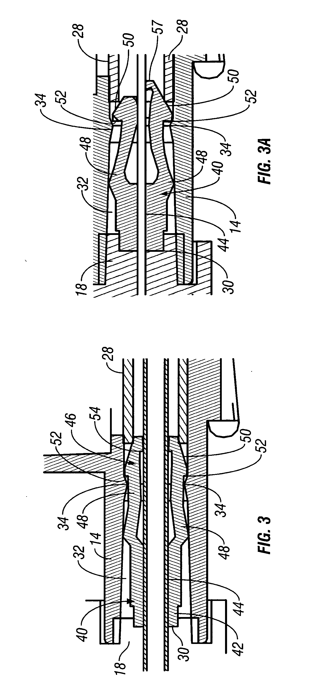
[0007] The foregoing objectives may be achieved by a needle safety device for an intravenous catheter apparatus having a base capable of receiving a needle and two opposing jaws attached to the base capable of being influenced by the needle. The two opposing jaws together form a reverse collet mechanism. The jaws are moveable between an expanded position with the effective outer diameter of the jaws increased when the needle is between the jaws and a collapsed position when the needle is not between the jaws. The jaws of the needle safety device permit relative movement of the needle with the base when the jaws are expanded. The jaws close around the needle tip as the needle slips through the space between the jaws. The jaws prevent relative movement of the needle with the base when the jaws are collapsed.
[0010] According to another feature of the present invention, the jaws have a side perpendicular to the cylindrical side of the wing housing that prevents movement past an obstruction of the intravenous catheter apparatus while the needle safety device is in an expanded position.
[0013] According to another feature of the present invention, the intravenous catheter apparatus has a cylindrical wing housing. The needle safety device fitting efficiently within the cylindrical wing housing.

Problems solved by technology

Medical professionals encounter numerous occupational hazards when administering care to patients.
One serious hazard is the accidental pricking by a needle after removing from an intravenous catheter.
Accidental pricking of medical professionals' skin by the needle is particularly hazardous because the needle tip easily penetrates the latex gloves used by the medical professionals.
The prior art recognizes that the needle tip guard is placed upon the needle after the needle is being withdrawn from the catheter; however, the prior art is difficult to assemble, utilizes an awkward tapered wing housing that requires it to be wider than necessary, utilizes complicated structures and has other disadvantages.

Method used


Image

  • Needle safety device for an intravenous catheter apparatus and method of use
  • Needle safety device for an intravenous catheter apparatus and method of use
  • Needle safety device for an intravenous catheter apparatus and method of use

Examples


Embodiment Construction

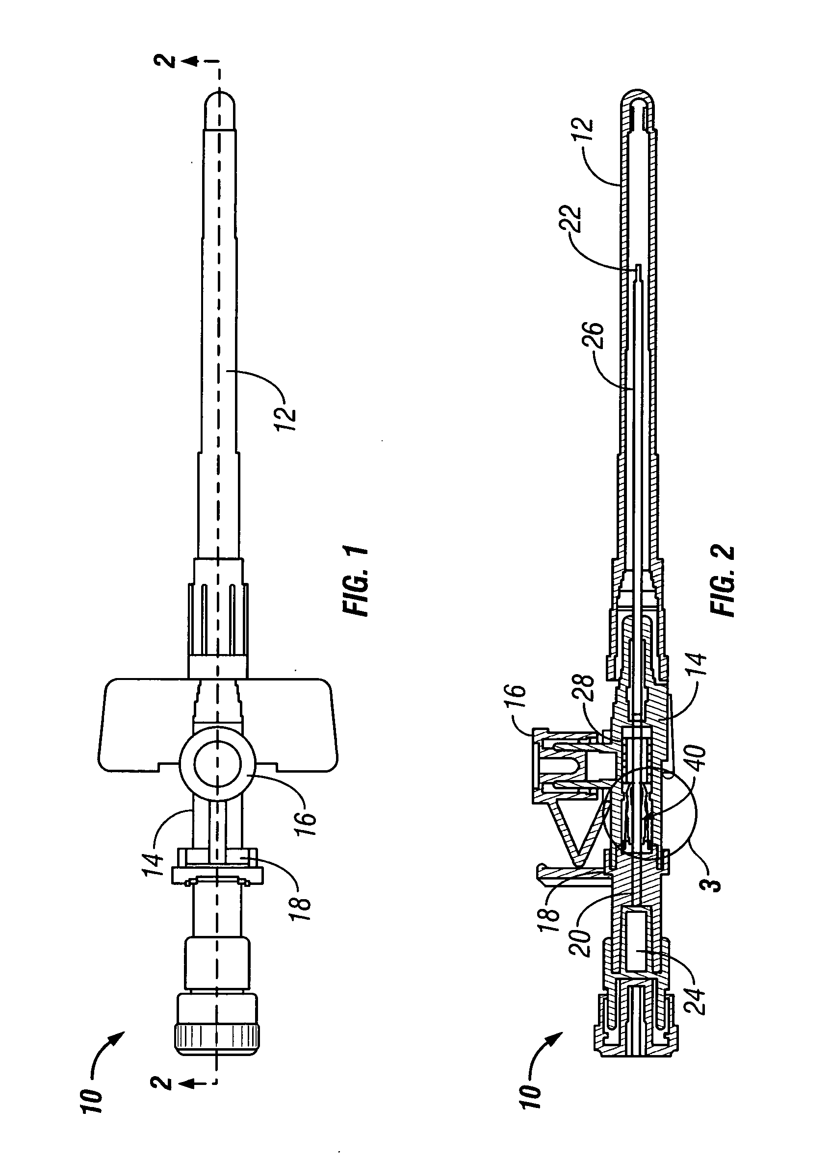
[0030] Referring to FIG. 1, an intravenous (IV) catheter apparatus 10 of the present invention is shown. The IV catheter apparatus is viewed as a finished product prior to use and includes a needle cover 12, a wing housing 14, a port cap 16 in unitary assembly with the wing housing 14, and a needle hub 18 attached to the wing housing 14.

[0031] As seen in the cross section depicted in FIG. 2, a needle 20 extends from the needle hub 18 through the wing housing and ends in a needle tip 22 under the needle cover 12.

[0032] The needle 20 is hollow and the needle tip 22 is typically cut at a diagonal. When the needle tip 22 is inserted into a patient the needle may encounter fluid pressure which travels through the needle tip 22 through the needle 20 and enters a flash back chamber 24.

[0033] Surrounding the needle is a catheter 26 which is attached to the wing housing 14 by catheter base 28. The catheter 26 is a flexible tube that will remain in the user to provide fluids, nourishment, ...


PUM


Abstract

A needle safety device for an intravenous catheter apparatus that includes a base capable of receiving a needle into opposing jaws attached to the base and capable of being influenced by the needle. The jaws move between an expanded position which interact with an obstruction within a wing housing of the intravenous catheter apparatus. The jaws permit relative movement of the needle with the base when expanded, close around a needle tip as it passes the jaws, and prevent relative movement of the needle with the base when the jaws are collapsed. The needle of the intravenous catheter apparatus may then be safely disposed with the needle tip within the needle safety device.

Description

BACKGROUND OF THE INVENTION [0001] The present invention relates to a guard for the needle tip of an intravenous (IV) catheter. In particular, the invention relates to a needle safety device that automatically covers the needle during withdrawal from the patient to prevent accidental contact with medical professionals. [0002] Medical professionals encounter numerous occupational hazards when administering care to patients. One serious hazard is the accidental pricking by a needle after removing from an intravenous catheter. Accidental pricking of medical professionals' skin by the needle is particularly hazardous because the needle tip easily penetrates the latex gloves used by the medical professionals. The concern for accidental pricking is of particular concern in this era of blood borne disease such as Hepatitis or AIDS. Previous needle tip guards have been manufactured that recognize the need for covering the needle tip when being withdrawn from the catheter. The prior art reco...

Claims


Application Information

Patent Timeline
IPC IPC(8): A61M5/178A61M5/32A61M25/06
CPCA61M5/3273A61M25/0693A61M25/0618A61M25/0606
Inventor DAGA, NEHA
Owner RISHI BAID
Learn More