Stent delivery system with imaging capability

a stent and imaging capability technology, applied in the field of medical devices, can solve the problems of large space, cumbersome procedure, and difficulty in using an endoscope to deliver a guidewire (and hence a stent delivery catheter) in some applications, and achieve the effect of improving the accuracy and reliability of the stent delivery catheter, reducing the risk of infection, and improving the safety of patients

Inactive Publication Date: 2005-12-15
BOSTON SCI SCIMED INC
View PDF23 Cites 64 Cited by
  • Summary
  • Abstract
  • Description
  • Claims
  • Application Information

AI Technical Summary

Benefits of technology

[0012] According to the present invention, various embodiments of a stent delivery system adapted to accommodate both a guidewire and a small-diameter fiber optic cable are provided. The use of a fiber optic cable with an imaging capability permits a physician to visually observe not only the proper advancement and placement of the guidewire but also the proper deployment of a stent before, during, and after the deployment procedure. Thus, the present invention provides a compact stent delivery system, which reduces the need for using fluoroscopy or a relatively larger-diameter endoscope to deliver and deploy a stent.

Problems solved by technology

Thus, the use of an endoscope to deliver a guidewire (and hence a stent delivery catheter) becomes difficult in some applications.
Furthermore, positioning an endoscope along the side of a stent to observe its proper deployment requires an even larger space, which is not always available.
Still further, use of fluoroscopy to confirm proper positioning of a guidewire and / or a stent is a relatively cumbersome procedure and requires additional safety mechanisms for the patients as well as the doctors and their assistants.

Method used


Image

  • Stent delivery system with imaging capability
  • Stent delivery system with imaging capability
  • Stent delivery system with imaging capability

Examples


Embodiment Construction

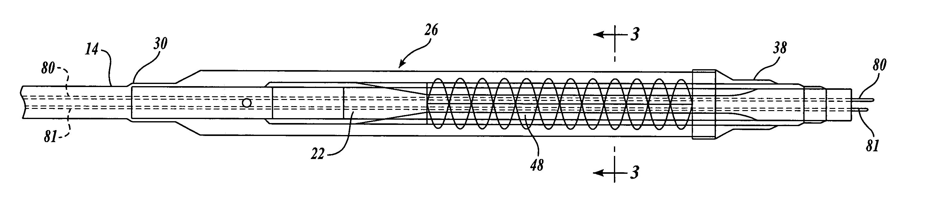
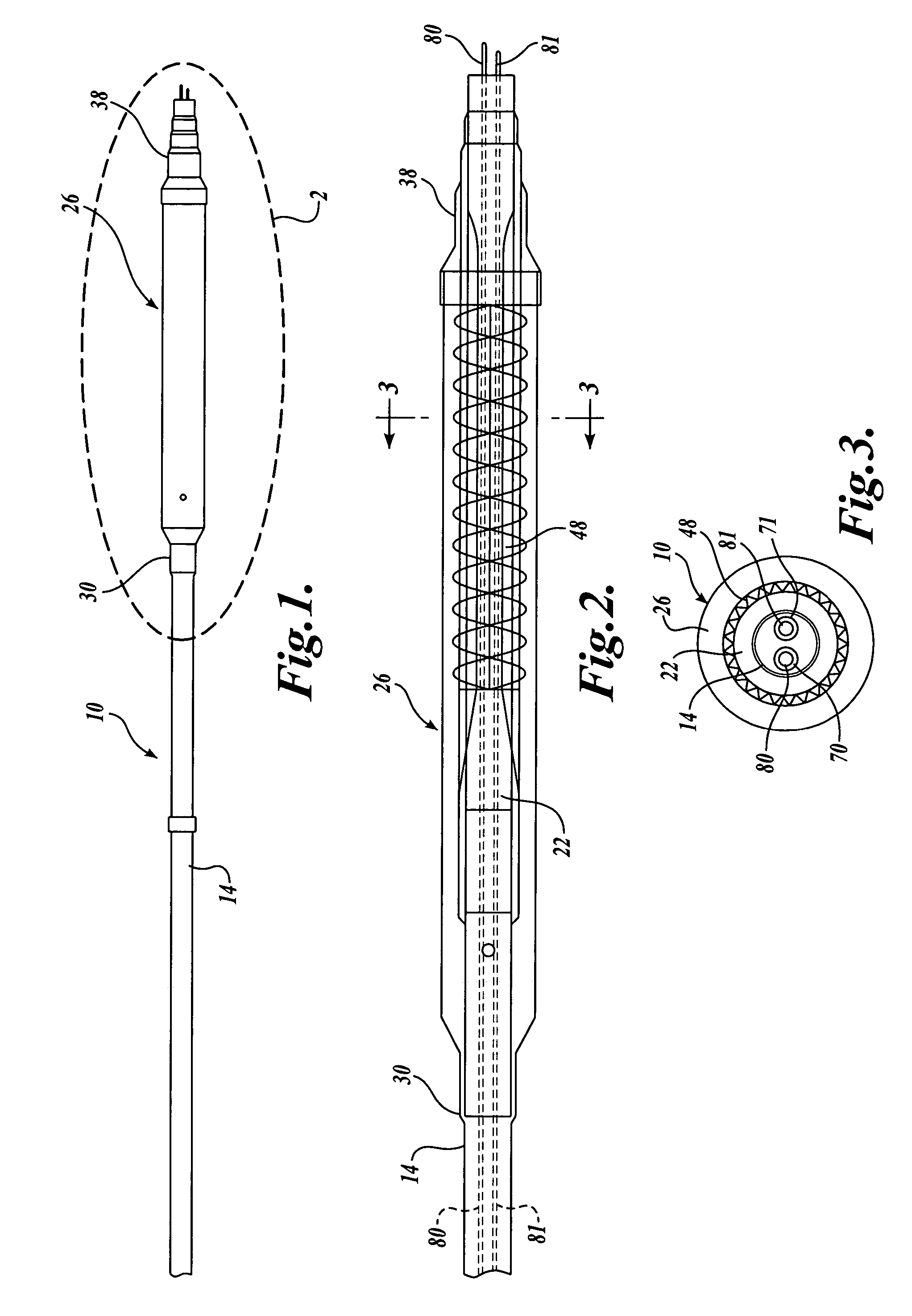
[0026]FIGS. 1-3 illustrate an inflation-type stent delivery system formed in accordance with the present invention. Referring to FIG. 1, a stent delivery system 10 has a catheter shaft 14 formed of any suitable flexible material, such as extruded plastic (e.g., polytetrafluoroethylene, polyether block amide, nylon, etc.). At the distal portion of the shaft 14 is disposed a sheath 26 coaxially surrounding the shaft 14. Referring additionally to FIG. 2, the distal portion of the shaft 14 is coupled to a balloon 22, which is constructed and arranged for expansion from a contracted state to an expanded state. The balloon 22 may be of any length depending on each application. The balloon 22 is shown in a folded, contracted state in FIG. 2. In use, the balloon 22 has a larger diameter which is obtained when the balloon 22 is expanded in any known manner. For example, the balloon 22 may be inflated by fluid (gas or liquid) from an inflation port (not shown) extending from an inflation lume...


PUM


Abstract

A stent delivery system includes a catheter shaft defining two lumens, for respectively receiving a guidewire and a fiber optic cable having a viewing capability. Specifically, the fiber optic cable has a first (e.g., proximal) end and a second (e.g., distal) end, and is adapted for transmitting illumination light from its first end to its second end while transmitting an image from its second end to its first end. The system further includes a stent positioned over the catheter shaft, and may also include means for deploying the stent. The stent may be of a self-expanding type or of an inflation type. The fiber optic cable is used to visually inspect proper deployment of the stent before, during, and after the stent deployment.

Description

FIELD OF THE INVENTION [0001] The present invention relates to medical devices, and in particular to a stent delivery system adapted for advancing a guidewire and a fiber optic cable having an imaging capability. BACKGROUND OF THE INVENTION [0002] Stents and stent delivery assemblies are utilized in a number of medical procedures and situations, and as such their structure and function are well known. A stent is a generally cylindrical prosthesis that is introduced via a catheter into a lumen of a body cavity or vessel. The stent is introduced into the cavity or vessel with a generally reduced diameter and then is expanded to the diameter of the cavity or vessel. In its expanded configuration, the stent supports and reinforces the cavity / vessel walls while maintaining the cavity / vessel in an open, unobstructed condition. [0003] Both self-expanding and inflation (as by a balloon) expandable stents are well known and widely available. Self-expanding stents must be maintained under pos...

Claims


Application Information

Patent Timeline
Patent Type & Authority Applications(United States)
IPC IPC(8): A61B1/04A61F2/06A61F2/84A61M25/00
CPCA61B1/00165A61B1/042A61B1/0607A61F2/95A61M2025/004A61M25/0029A61M2025/0037A61M2025/0039A61F2/958
Inventor RICHARDSON, M. KEVIN
Owner BOSTON SCI SCIMED INC
Why Eureka
Try Eureka