Toilet tank automatic flush apparatus

a flushing apparatus and toilet tank technology, applied in the direction of flushing devices, water installations, constructions, etc., can solve the problem of no electric power in the household, and achieve the effect of convenient damped and malfunctioning

Inactive Publication Date: 2005-12-22
YEN CHIH CHEN
View PDF5 Cites 13 Cited by
  • Summary
  • Abstract
  • Description
  • Claims
  • Application Information

AI Technical Summary

Benefits of technology

[0006] The primary object of the present invention is to provide a toilet tank automatic flush apparatus to resolve the disadvanta...

Problems solved by technology

Thus it consumes no electric power except a little electric ...

Method used


Image

  • Toilet tank automatic flush apparatus
  • Toilet tank automatic flush apparatus
  • Toilet tank automatic flush apparatus

Examples


Embodiment Construction

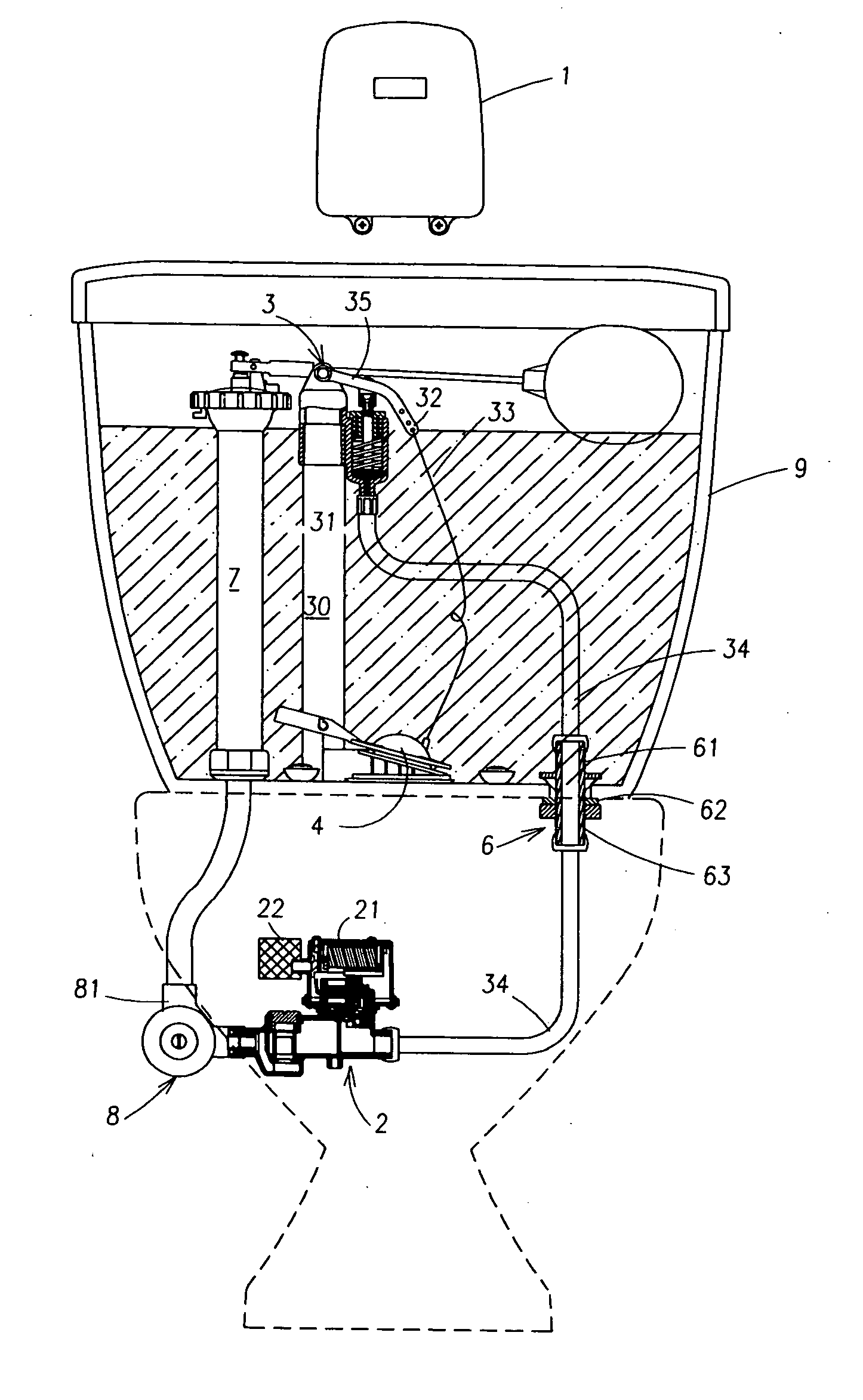
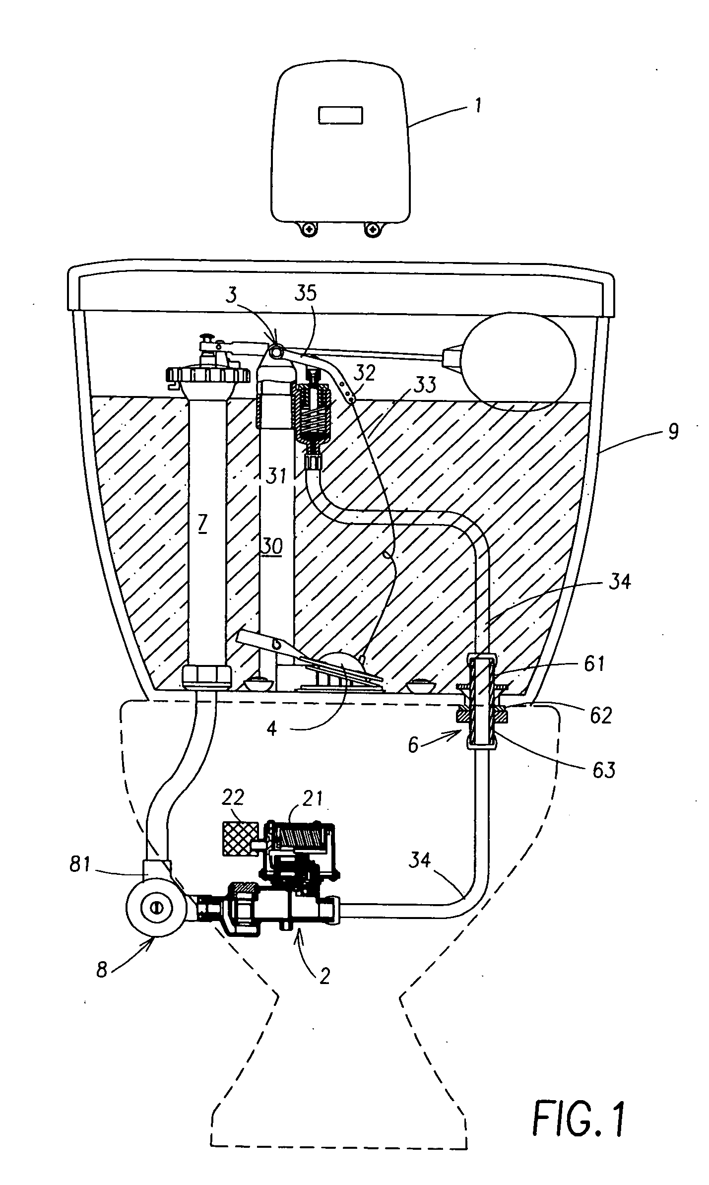
[0016] Referring to FIG. 1, the automatic toilet tank flush apparatus according to the invention includes a detection module 1 to detect user's use condition and emit a control signal, a solenoid valve module 2 to receive the signal of the detection module 1 to activate hydraulic operation, and a flush module 3 installed in a water tank to be actuated by the detection module 1 through a hydraulic pressure to actuate a water discharge valve 4 for flushing.

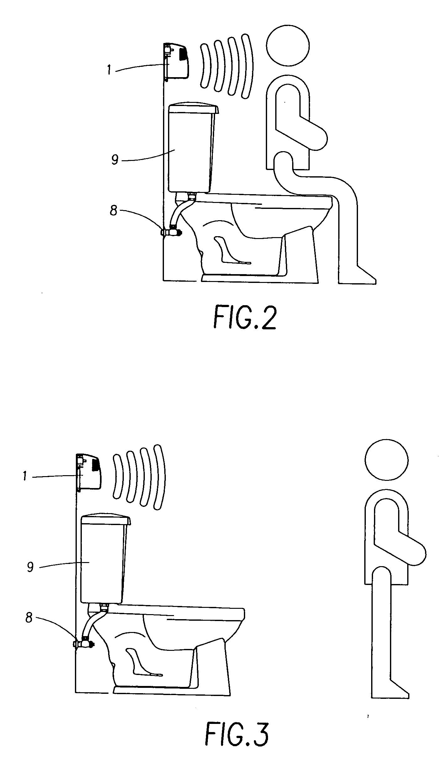
[0017] The detection module 1 is installed on a location sensible to users. In an embodiment of the invention, it is preferably located on a wall above the water tank 9. It includes photoelectric elements that can detect the presence of a user and user's use conditions. The detected result generates a flushing signal transmitted to the solenoid valve module 2 through a signal emission device.

[0018] The solenoid valve module 2 is located below the water tank 9 remote from the damp environment of the water tank to achieve normal ope...


PUM


Abstract

A toilet tank automatic flush apparatus includes a detection module located outside the toilet water tank, a solenoid valve module and a flush module. The solenoid valve module is located outside the water tank and connected to a water supply head, and is controlled by signals from the detection module to activate a solenoid valve switch to channel water from the water supply head into a hydraulic cylinder of the flush module through a tube to generate a hydraulic pressure to push a hydraulic arm upwards to lift a rocker arm. The rocker arm has a distal end fastening to a rope to connect and open a water discharge valve so that water in the water tank may be flushed into the toilet in a large quantity. The solenoid valve switch stops water supply after a preset time period. A spring located in the hydraulic cylinder pushes the hydraulic arm and the rocker arm downwards to release the rope so that the water discharge valve may be closed and water may flow into the water tank again.

Description

BACKGROUND OF THE INVENTION [0001] 1. Field of the Invention [0002] The present invention relates to an automatic flush apparatus that has a detection device to control a solenoid valve to channel water supply to generate a hydraulic pressure to actuate a flush module in a water tank that has a rocker arm to actuate a water discharge valve to perform flushing. [0003] 2. Description of the Prior Art [0004] Water for flushing toilets generally is stored in a water tank or a flush tube. Flush control is done manually or by electric detection. In the known techniques for flushing toilets, using the flush tube generally is controlled manually or by electric detection. In the case of using the water tank to supply water for flushing, manual control is still the most widely used approach. Automatic electric control is still not widely adopted. This mainly results from the concern that electronic elements tend to be short circuit and malfunction when exposed to the damp environment in the w...

Claims


Application Information

Patent Timeline
IPC IPC(8): E03D5/10
CPCE03D5/10
Inventor YEN, CHIH-CHEN
Owner YEN CHIH CHEN
Why Eureka
Try Eureka