Substrate processing apparatus

a substrate processing and apparatus technology, applied in the direction of coatings, chemical vapor deposition coatings, metallic material coating processes, etc., can solve the problems of reducing the operation rate of the apparatus, significantly lowering the manufacturing efficiency of the substrate, and reducing the safety standards of the coating and developing treatment apparatus. safety, the effect of ensuring the safety of the operator when performing maintenance of the substrate uni

Inactive Publication Date: 2005-12-22
TOKYO ELECTRON LTD
View PDF3 Cites 13 Cited by
  • Summary
  • Abstract
  • Description
  • Claims
  • Application Information

AI Technical Summary

Benefits of technology

[0010] The present invention has been developed in consideration of the above points, and its object is to provide a substrate processing apparatus capable of increasing the operation efficiency of the apparatus while ensuring the safety of an operator who performs maintenance.
[0012] According to the present invention, in the event of occurrence of a poor condition, for example, in the substrate unit in the casing, the shut-off mechanism operating member can operate the shut-off mechanism to shut the first space where the substrate unit exists off from the second space in the casing. Accordingly, when the operator detaches the outer wall panel, the first space where the substrate unit exists is shut off from the remaining second space where the substrate carrier unit exists, so that the safety of the operator is ensured even if the substrate carrier unit is operating. At this time, the operator is not allowed to access the substrate carrier unit in operation, whereby the safety standards of the apparatus can also be met. On the other hand, when the first space is shut off from the second space, the interlock mechanism becomes disabled, so that the outer panel can be detached to perform maintenance of the substrate unit with, for example, the substrate carrier unit within the second space carrier unit being operating. Accordingly, the other operation in the casing can be continued, while maintenance is being performed, for example, for the substrate unit. As a result of this, the operation rate of the substrate processing apparatus can be improved.
[0014] According to the present invention, when a poor condition occurs, for example, in the substrate unit in the casing, the shutter opens the opening portion of the casing to allow the operator to perform work for the substrate carrier unit. In this event, the substrate carrier unit cannot access the substrate unit because the casing on the substrate carrier path side between the substrate unit and the substrate carrier unit is shut. Accordingly, the safety of the operator when performing maintenance of the substrate unit can be ensured. Further, since the operator cannot access the substrate carrier unit in operation, the safety standards of the apparatus can also be met. On the other hand, when the shutter shuts the substrate carrier path, the interlock mechanism becomes disabled, so that the operator can perform maintenance of the substrate unit with, for example, the substrate carrier unit being operating. Accordingly, the other operation in the casing can be continued, while maintenance is being performed, for example, for the substrate unit. As a result of this, the operation rate of the substrate processing apparatus can be improved.
[0015] According to the present invention, it is possible to improve the operation efficiency of the substrate processing apparatus while ensuring the safety of the operator who performs maintenance for the substrate processing apparatus.

Problems solved by technology

In this event, it is dangerous if the operator inserts his or her hand or face into the casing during operation of the substrate carrier unit.
Moreover, an apparatus design that allows an ordinary operator to access the substrate carrier unit in operation is not permitted in terms of safety standards of the coating and developing treatment apparatus.
However, if the motion of the whole apparatus is stopped, for example, while a plurality of substrates are under processing in the coating and developing treatment apparatus, all of the substrates under processing existing in the apparatus can result in defectives.
This has required waiting time and maintenance time until after the substrates are returned into the loader / unloader section every time maintenance is performed because of occurrence of a poor condition in the coating and developing treatment apparatus.
Further, even a breakage of only a portion in the coating and developing treatment apparatus has also required stop of the whole apparatus to perform maintenance, thus decreasing the operation rate of the apparatus to result in a significantly lowered manufacturing efficiency of substrates.
In particular, in the coating and developing treatment apparatus incorporating the above-described inspection units, poor conditions associated with the inspection unit are apt to occur and require a larger number of times of maintenance, leading to a significant decrease in manufacturing efficiency.
Some coating and developing treatment apparatuses include a release key for the interlock mechanism, and persons who can release the interlock mechanism and access the inside of the apparatus are limited to those having a predetermined qualification according to rules in place.
Therefore, when an ordinary operator performs maintenance, the operator can only stop the whole apparatus to perform maintenance.
As has been described, in the conventional coating and developing treatment apparatus, the safety of the operator during maintenance has been ensured, whereas much recovery time has been required due to the poor condition in the apparatus to result in a decrease in the operation efficiency of the apparatus.

Method used


Image

  • Substrate processing apparatus
  • Substrate processing apparatus
  • Substrate processing apparatus

Examples


Embodiment Construction

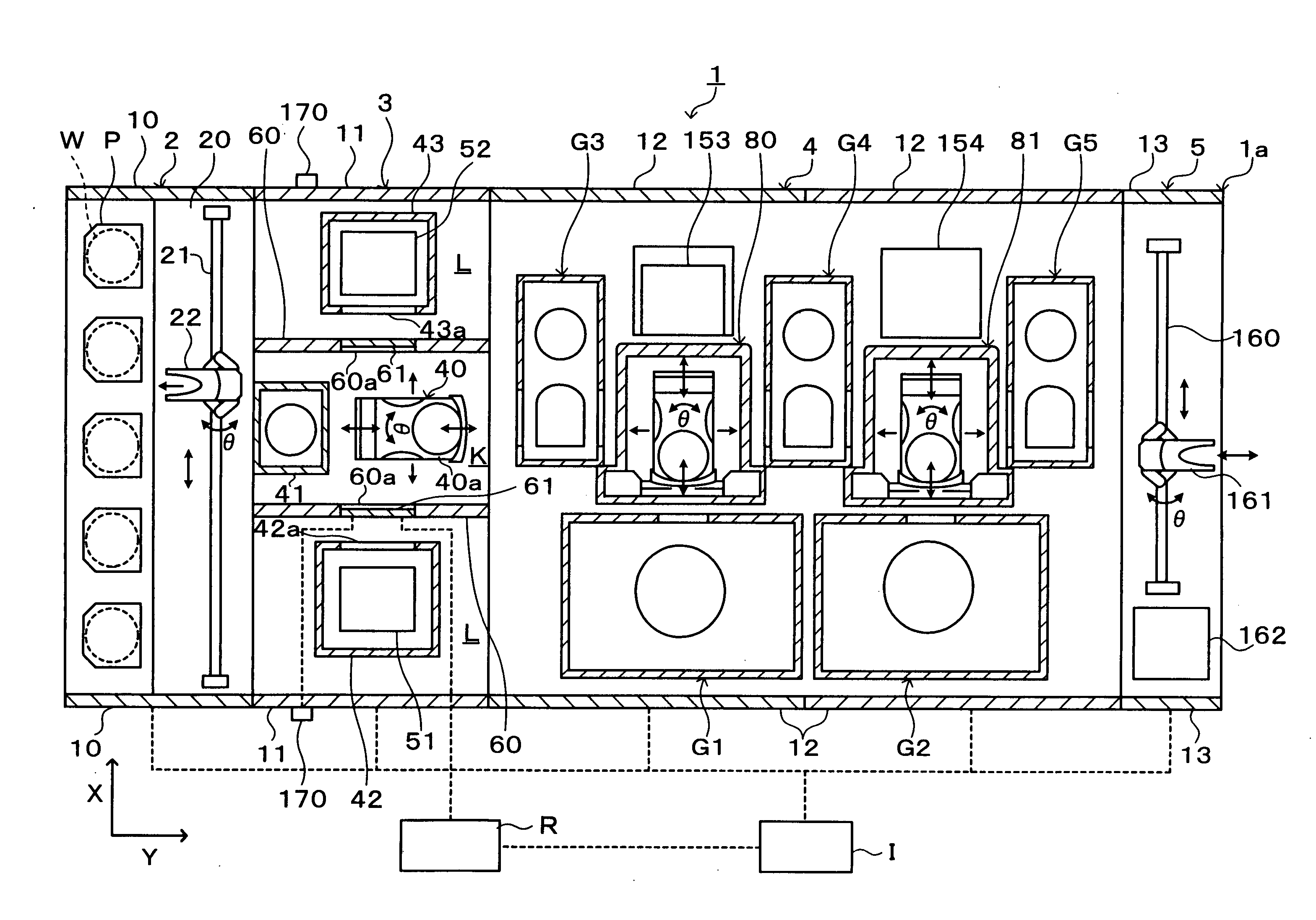
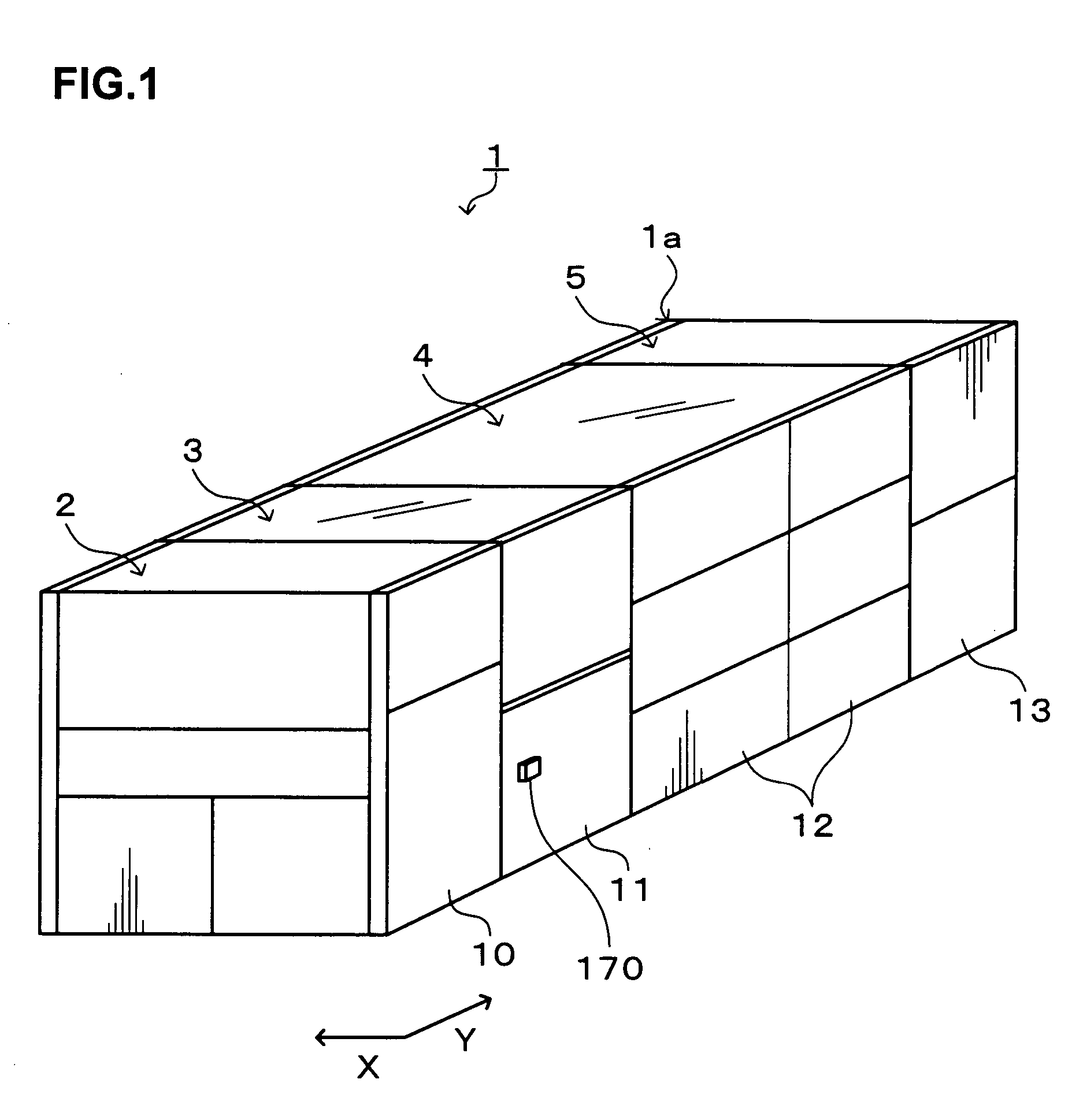
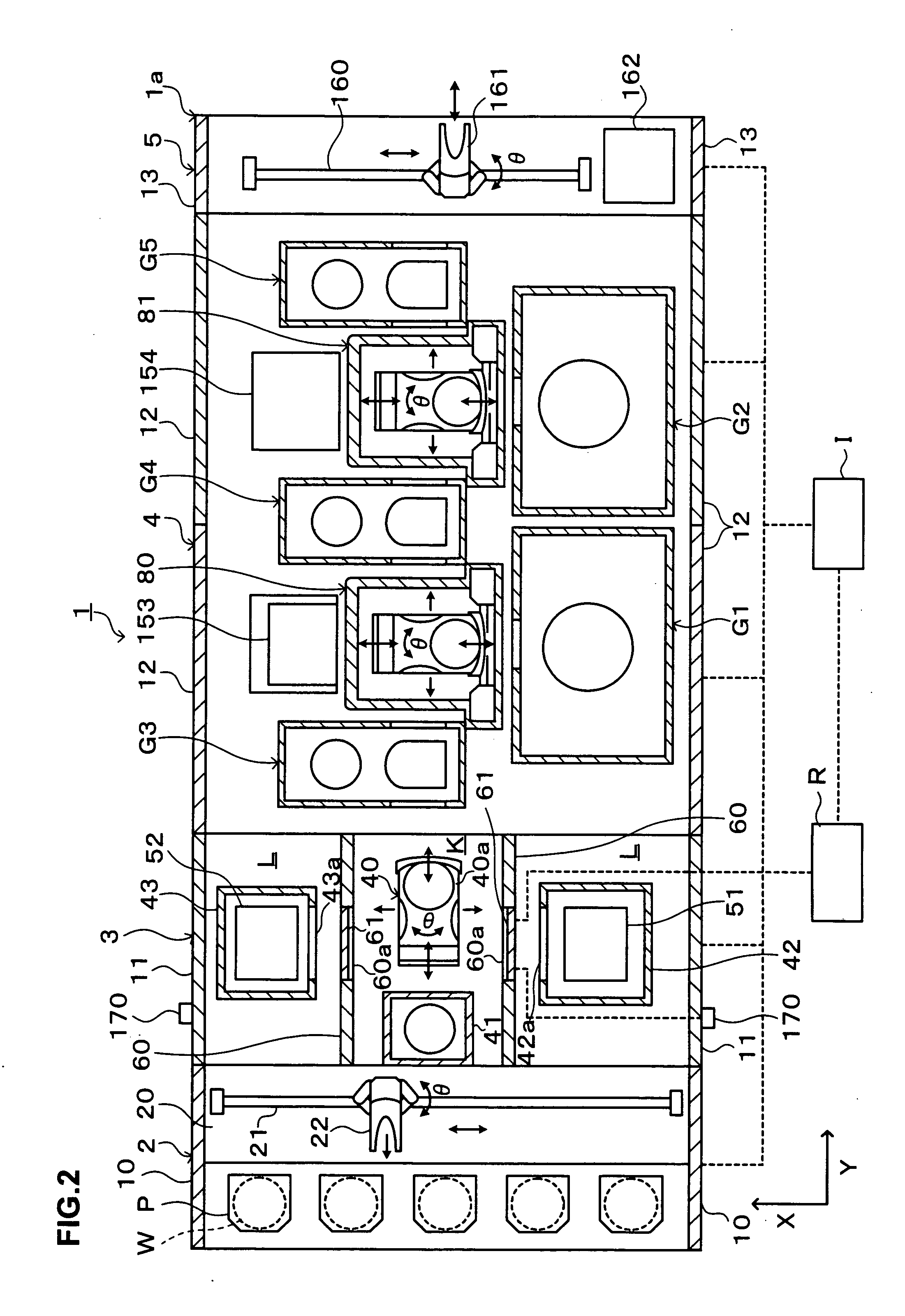
[0028] Hereinafter, a preferred embodiment of the present invention will be described. FIG. 1 is a perspective view showing the outline of a configuration of a coating and developing treatment apparatus 1 as a substrate processing apparatus according to the embodiment, FIG. 2 is an explanatory view of a cross section showing the outline of the configuration of the coating and developing treatment apparatus 1, FIG. 3 is a front view of the coating and developing treatment apparatus 1, and FIG. 4 is a rear view of the coating and developing treatment apparatus 1.

[0029] The coating and developing treatment apparatus 1 is entirely covered by a casing 1a being an outer wall so that the inside of the coating and developing treatment apparatus 1 is enclosed as shown in FIG. 1. Inside the casing 1a of the coating and developing treatment apparatus 1, for example, a cassette station 2 as a carry-in / out section for carrying, for example, 25 wafers W per cassette, as a unit of cassette P, fro...


PUM

PropertyMeasurementUnit
heightaaaaaaaaaa
shapeaaaaaaaaaa
thicknessaaaaaaaaaa

Abstract

An object of the present invention is to improve the operation efficiency of a substrate processing apparatus while ensuring the safety of an operator who performs maintenance of the apparatus. The present invention is a substrate processing apparatus including a substrate unit capable of housing a substrate and a substrate carrier unit for carrying the substrate to the substrate unit, in a casing, including: an outer wall panel detachably attached to the casing at a position opposed to the substrate unit; a shut-off mechanism capable of shutting a first space within which the substrate unit is located off from a second space other than the first space within which the substrate carrier unit is located, in the casing, the first space being opened to the outside of the casing by detaching the outer wall panel; a shut-off mechanism operating member for operating the shut-off mechanism to shut the first space off from the second space; and an interlock mechanism for stopping motion of the whole in the casing when the outer wall panel is detached. The apparatus has an interlock disabling mechanism for disabling the interlock mechanism when the shut-off mechanism shuts the first space off from the second space.

Description

BACKGROUND OF THE INVENTION [0001] 1. Field of the Invention [0002] The present invention relates to a substrate processing apparatus. [0003] 2. Description of the Related Art [0004] Photolithography process in a manufacturing process of, for example, a semiconductor device is usually performed using a coating and developing treatment apparatus. In recent years, there has been a proposed coating and developing treatment apparatus in which a loader / unloader section for carrying in / out a substrate to / from a casing, an inspection section for performing various inspections for the substrate; a processing section for performing a plurality of kinds of processing and treatments such as a resist coating treatment, developing treatment, thermal processing, and so on, and an interface section for delivering the substrate to / from the processing section and an aligner, are arranged in series (see Japanese Patent Application Laid-open No. 2002-26107). A plurality of inspection units are arrange...

Claims


Application Information

Patent Timeline
Patent Type & Authority Applications(United States)
IPC IPC(8): C23C16/00C23F1/00H01L21/00
CPCH01L21/67126H01L21/67184H01L21/67178H01L21/02
Inventor YAMASHITA, MASAMINAKASHIMA, SEIJI
Owner TOKYO ELECTRON LTD
Why Eureka
Try Eureka