Methods and systems for heating thermal storage units

a technology of thermal storage unit and method, which is applied in the direction of water heater, steam generation using hot heat carriers, lighting and heating apparatus, etc., can solve the problems of high standby loss, difficult repair of radiant heaters, and high space requirements, so as to reduce the amount of time

Inactive Publication Date: 2005-12-22
ACTIVE POWER INC
View PDF9 Cites 45 Cited by
  • Summary
  • Abstract
  • Description
  • Claims
  • Application Information

AI Technical Summary

Benefits of technology

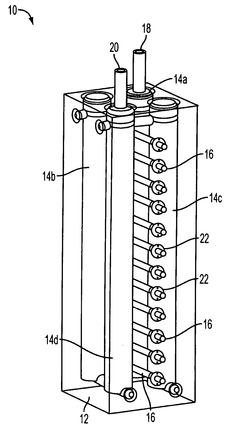
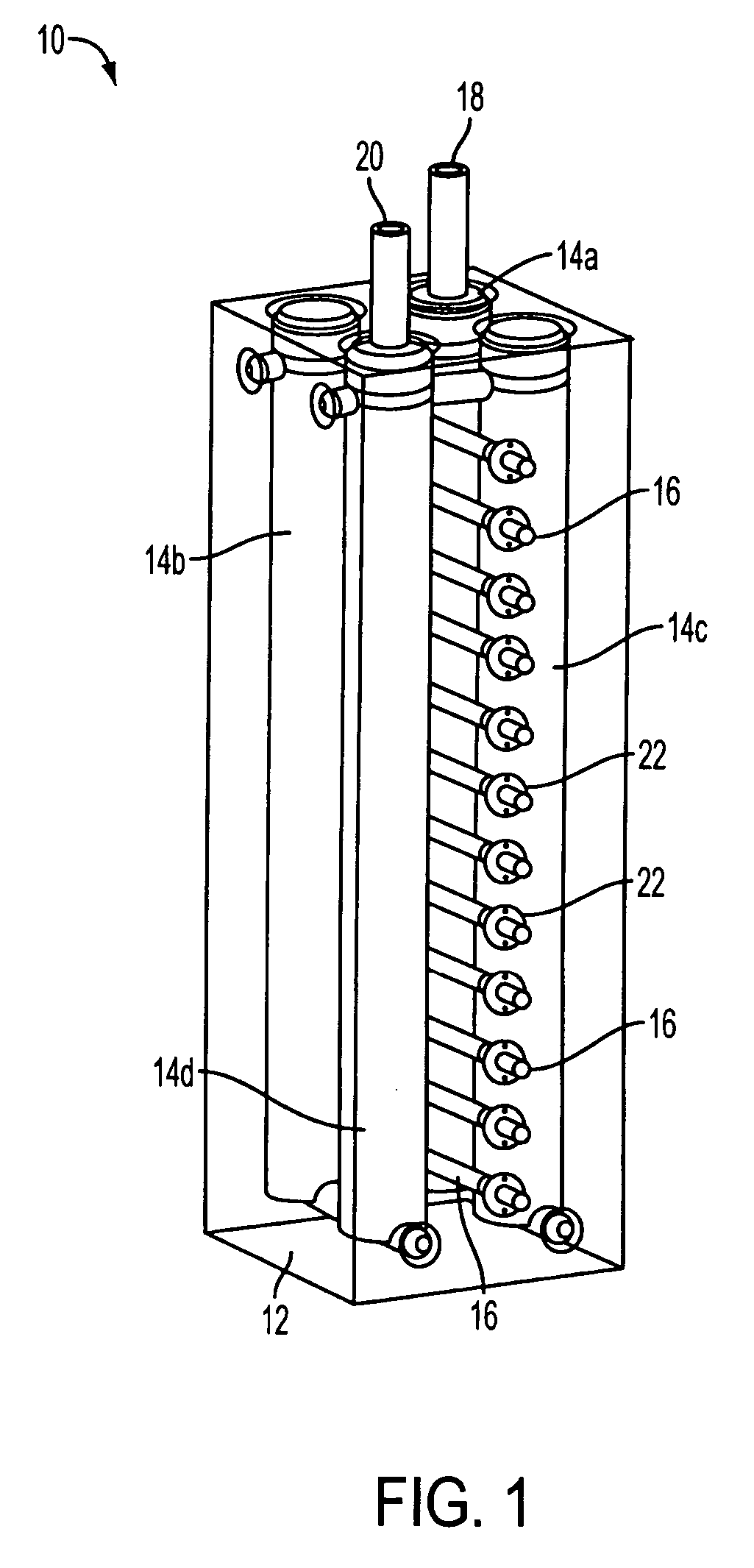
[0018] In view of the foregoing, it is an object of the present invention to provide methods and systems for heating a TSU with compact size and reduced standby losses.
[0019] It further is an object of the present invention to provide methods and systems for easily replacing and repairing the heating system of a TSU assembly without requiring additional personnel and / or special tools.
[0020] It even further is an object of the present invention to provide methods and systems for continuously heating a TSU without significant loss in the overall uniformity of the temperature of the TSU even when the heating system malfunctions.

Problems solved by technology

Disadvantageously, radiant heaters may waste a lot of energy by emanating heat to the ambient environment outside the TSUs, resulting in high standby losses.
This, however, occupies valuable space in a TACAS system, in which space is at a premium.
Radiant heaters also are difficult to repair, requiring removal of the thick insulation surrounding the radiant heater and requiring additional personnel and / or special tools to maneuver the nearly half ton TSU out of the TACAS cabinet.
When a radiant heater malfunctions, there often is significant loss in the overall uniformity of the temperature in the TSU, thereby requiring the TACAS system to be shutdown immediately for repair.
During this time period, the TACAS system is offline and unable to provide backup power.

Method used


Image

  • Methods and systems for heating thermal storage units
  • Methods and systems for heating thermal storage units
  • Methods and systems for heating thermal storage units

Examples


first embodiment

[0079] FIGS. 7A-G illustrate numerous embodiments of the heater puller of FIG. 6. FIG. 7A illustrates a heater puller. Plier-type heater puller 80 comprises coupler 82 and actuator 83. Coupler 82 includes two gripping surfaces 84 that conform to the shape of the proximal end of heater 16. Actuator 83 includes two handles 86a and 86b, each having a distal end that is coupled rigidly to one of the gripping surfaces, and pivot 88 about which the handles rotate. When the proximal ends of handles 86 are urged apart, handles 86 pivot about pivot 88 so that gripping surfaces 84 also move away from each other. Similarly, when the proximal ends of the handles are urged together, so too are the gripping surfaces. Thus, when a heater is placed between the gripping surfaces, heater puller 80 may be engaged securely to the heater by squeezing the handles together. While the heater puller is engaged to a heater, an operator can pull the heater from or push a heater into a TSU.

[0080] Optionally, h...

second embodiment

[0082]FIGS. 7C and 7D illustrate the heater puller. Ferrule-type heater puller 100 comprises sliding sleeve 102, ferrule 104 disposed at the distal end of sliding sleeve 102, center rod 106, and grips 108 that are mounted on compliant extensions 109 of center rod 104. Center rod 106 and grips 108 may be advanced into and out of center bore 110, which extends from the proximal end of sliding sleeve 102 to the distal end of ferrule 104, to respectively close and open grips 108. To open grips 108 (as shown in FIG. 7D), center rod 106 is advanced towards the distal end of sliding sleeve 102. The compliance of extensions 109 allows a heater to be inserted between grips 108. Sliding sleeve 102 and ferrule 104 then may be actuated in the distal direction towards heater 16 to close grips 108. Ferrule 104 engages compliant extensions 109, contracting the extensions (and thus grips 108) around heater 16 and thereby securely engaging the heater to heater puller 100. While the heater puller is ...

third embodiment

[0084] FIGS. 7E-F illustrates a heater puller. Notch-type heater puller 120 comprises actuator 122 and coupler 124 having one or more L-shaped slots 126. Each slot 126 incorporates detent 128 to slide past associated pin 130 disposed on the proximal end of heater 16. This permits pin(s) 130 to engage coupler 124 with reduced rotation. While the heater puller is engaged to the heater, an operator can pull the heater from or push a heater into a TSU. FIG. 7F provides an end view of heater 16 with two pins 130.


PUM


Abstract

Methods and systems for heating a thermal storage unit (TSU) are provided. A thermal storage system is provided that includes a system of heaters removably disposed at least partially within the TSU, a control system for adjusting power provided to the heaters, and a removal tool for removing one or more of the heaters from the TSU when the TSU is still hot. The thermal storage system may be used in a thermal and compressed air storage system for backup power applications.

Description

REFERENCE TO RELATED APPLICATIONS [0001] This application is a continuation-in-part of U.S. patent application Ser. No. 10 / 738,825 (hereinafter “the '825 patent application”), (Attorney Docket No. AP-46), filed Dec. 16, 2003, entitled “Thermal Storage Unit and Methods for Using the Same to Heat a Fluid,” the entirety of which is incorporated herein by reference.FIELD OF THE INVENTION [0002] The present invention relates to methods and systems for heating thermal storage units (TSUs) and managing a system of heaters in a manner that increases the operational life of the heaters and maintains the TSUs at desired operating conditions with less interruption. BACKGROUND OF THE INVENTION [0003] TSUs are well-known and often used in power delivery systems, such as compressed air storage (CAS) systems and thermal and compressed air storage (TACAS) systems. Such systems, often used to provide an available source of electrical power, often use compressed air to drive a turbine that powers an ...

Claims


Application Information

Patent Timeline
Patent Type & Authority Applications(United States)
IPC IPC(8): F24H1/18F24H7/04F24H9/20
CPCF24H9/2078F24H7/0416F24H15/25F24H15/37F24H15/395F24H15/20
Inventor HUDSON, ROBERT S.LOGAN, SCOTT D.WEAVER, MATTHEW D.BUNTON, RICHARD L.
Owner ACTIVE POWER INC
Why Eureka
Try Eureka