Electric tile modules

a technology of electric tile and modules, applied in the field of tiles, can solve the problems of slow production cost, slow silicon crystal growth, and high cost of forming thin (0.1-0.3 mm) wafers

Inactive Publication Date: 2005-12-22
BANISTER MARK
View PDF40 Cites 64 Cited by
  • Summary
  • Abstract
  • Description
  • Claims
  • Application Information

AI Technical Summary

Problems solved by technology

Providing electricity through photovoltaic and thermovoltaic cells is becoming more popular as these technologies have come down in cost and reliance on other sources of electric power is increasingly disfavored for environmental and strategic reasons.
However, providing a general use tile with electrical components that is easy to install and electrically connectable to other tiles without external wiring has been elusive.
The main proble

Method used


Image

  • Electric tile modules
  • Electric tile modules
  • Electric tile modules

Examples


Embodiment Construction

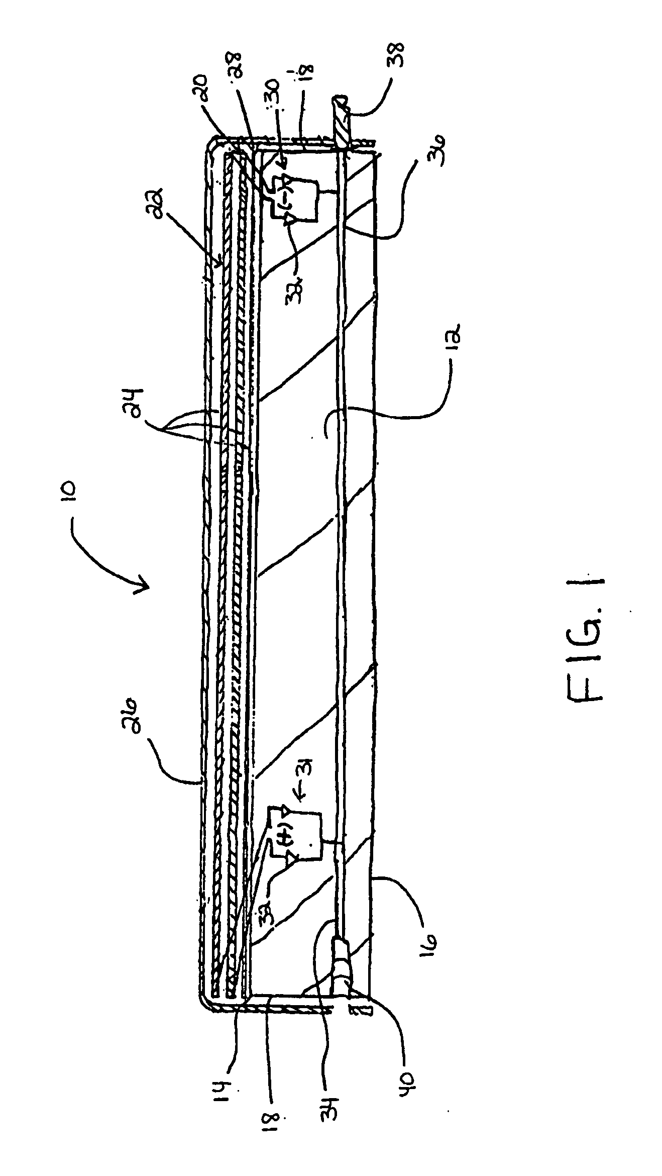
[0032] The invention, in general, provides an electrically connectable tile module 10. FIG. 1 is a cross-sectional side view of the electrically connectable tile module 10 with electrical components drawn in schematic form, in accordance with a first exemplary embodiment of the invention. The electrically connectable tile module 10 includes a rigid substrate 12. The rigid substrate 12 may include ceramic, cement, or other rigid materials, including, but not limited to, clay, mud, polymers such as a plastic, polymer / clay or polymer / ceramic hybrids, or glass. The rigid substrate 12 may be composed of an electrically insulating material to prevent short circuits among connected tiles modules. Rigid substrate 12 includes a top side 14, a bottom side 16, and side edges 18. Although a substantially rectangular cross-sectional shape for the rigid substrate 12 is shown, it should be understood that the tile modules may assume any shape having top and bottom sides 14, 16 and one (e.g., circl...


PUM


Abstract

The electrically connectable tile module includes a porous substrate having a top side, a bottom side, and at least two side edges. At least one connector is integrated into the porous substrate allowing adjoining electrically connectable tile modules to be electrically connected to the porous substrate. At least one electrical element is disposed over the top side of the porous substrate and electrically connected to the at least one connector.

Description

CROSS-REFERENCE TO RELATED APPLICATION [0001] This application claims priority to copending U.S. patent application entitled, “Multi-Use Electric Tile Modules”, having Ser. No. 10 / 222,483 filed Aug. 16, 2002, which is entirely incorporated herein by reference.FIELD OF THE INVENTION [0002] The invention generally relates to tiles for wall, roof and floor applications. More particularly, the invention relates to connectable tile modules that include electrical components. BACKGROUND OF THE INVENTION [0003] Providing electricity through photovoltaic and thermovoltaic cells is becoming more popular as these technologies have come down in cost and reliance on other sources of electric power is increasingly disfavored for environmental and strategic reasons. However, providing a general use tile with electrical components that is easy to install and electrically connectable to other tiles without external wiring has been elusive. [0004] The conversion of electromagnetic radiation from the...

Claims


Application Information

Patent Timeline
IPC IPC(8): E04D13/18H01L31/042H01L31/048H01L31/058
CPCE04D2001/308E04F2290/026H01L31/052Y02B10/12H02S20/25Y02B10/70Y02E10/50E04F2011/1048H02S40/38Y02B10/20H02S40/42H02S40/425Y02B10/10Y02E70/30
Inventor BANISTER, MARK
Owner BANISTER MARK
Why Eureka
Try Eureka