Automatic tire pressurizing device

a pneumatic tire and air compression technology, which is applied in the measurement of tires, vehicle components, transportation and packaging, etc., can solve the problems of slow air leakage from tires, vehicle performance may be worsened, and vehicle becomes dangerous for users and fellow road users, so as to reduce the volume and diminish the compression of air

Inactive Publication Date: 2005-12-22
FORD GLOBAL TECH LLC
View PDF4 Cites 9 Cited by
  • Summary
  • Abstract
  • Description
  • Claims
  • Application Information

AI Technical Summary

Benefits of technology

[0005] The advantage of the invention lies in that the pressurizing device automatically refills the tire and compensates for any pressure loss due to minor and normal leakage. Testing has shown that it is normal for a car tire to loose 15% of a predetermined tire pressure of 2 bar during 1 year when driving 2000 km. The irregularities in the surface may cause pressure increase peaks of about 20% of the tyre pressure. The pressure peaks causes enough movement of the membrane to cause compression of air in the compression unit.
[0006] According to one embodiment the inner space comprises an outer chamber comprising the compression chamber and a balancing chamber. The balancing chamber is in fluid communication with ambient air via a balancing chamber conduit, enabling a neutral air pressure in the balancing chamber.
[0007] According to one embodiment the membrane is arranged to be balanced against the tire pressure in the pressure chamber by a first resilient means such that the membrane, compared to the reference position, has the negative position when the tire pressure is lower than the predetermined tire pressure and a positive position when the tire pressure is above the predetermined tire pressure. Both the negative and the positive positions are relative positions that changes with the tire pressure.
[0008] The compression unit is advantageously arranged such that when the membrane is in the negative position the compression chamber is in fluid communication with ambient air via an air intake conduit and such that when the membrane is in a positive position the compression chamber is hindered from fluid communication with the ambient air. Since the compression chamber in the positive position is hindered from fluid communication with ambient air, the air in the compression chamber may be compressed by the compression chamber diminishing its volume.
[0009] According to one embodiment the compression unit comprises a piston and the compression chamber. The piston is attached to the membrane and extends from the membrane into the compression chamber. The compression chamber has an inner circumferential geometry corresponding to the outer circumferential feature of the piston. The outer circumferential dimension of the piston may advantageously be smaller than the inner circumferential dimension of the compression chamber, such that the piston may slide with an acceptable degree of friction in the compression chamber. The gap width between the piston and compression chamber cannot be so large that the air in the compression chamber may leak during the compression phase, because this would diminishing the compression of the air in the compression chamber.
[0010] According to one embodiment the piston is cylindrical with two opposing first and second end surfaces and a therebetween extending envelope surface. The piston comprises a first conduit extending from a first opening in the first end surface to a second opening, and a second conduit extending from the second opening to a third opening in the second end surface. The piston may in another embodiment have another cross-section than a circular, for example, oval, rectangular, or triangular. The cross-section of the compression chamber will of course vary with the cross-section of the piston.

Problems solved by technology

One problem with the wheel arrangements of today is that air slowly leaks from the tire.
If the user neglects to always keep the tire pressure as close to the predetermined value as possible, the performance of the vehicle may be worsened.
If the tire pressure gets too low, the vehicle may perform so bad at high speeds that the vehicle becomes dangerous for the user and for fellow road users.

Method used


Image

  • Automatic tire pressurizing device
  • Automatic tire pressurizing device
  • Automatic tire pressurizing device

Examples


first embodiment

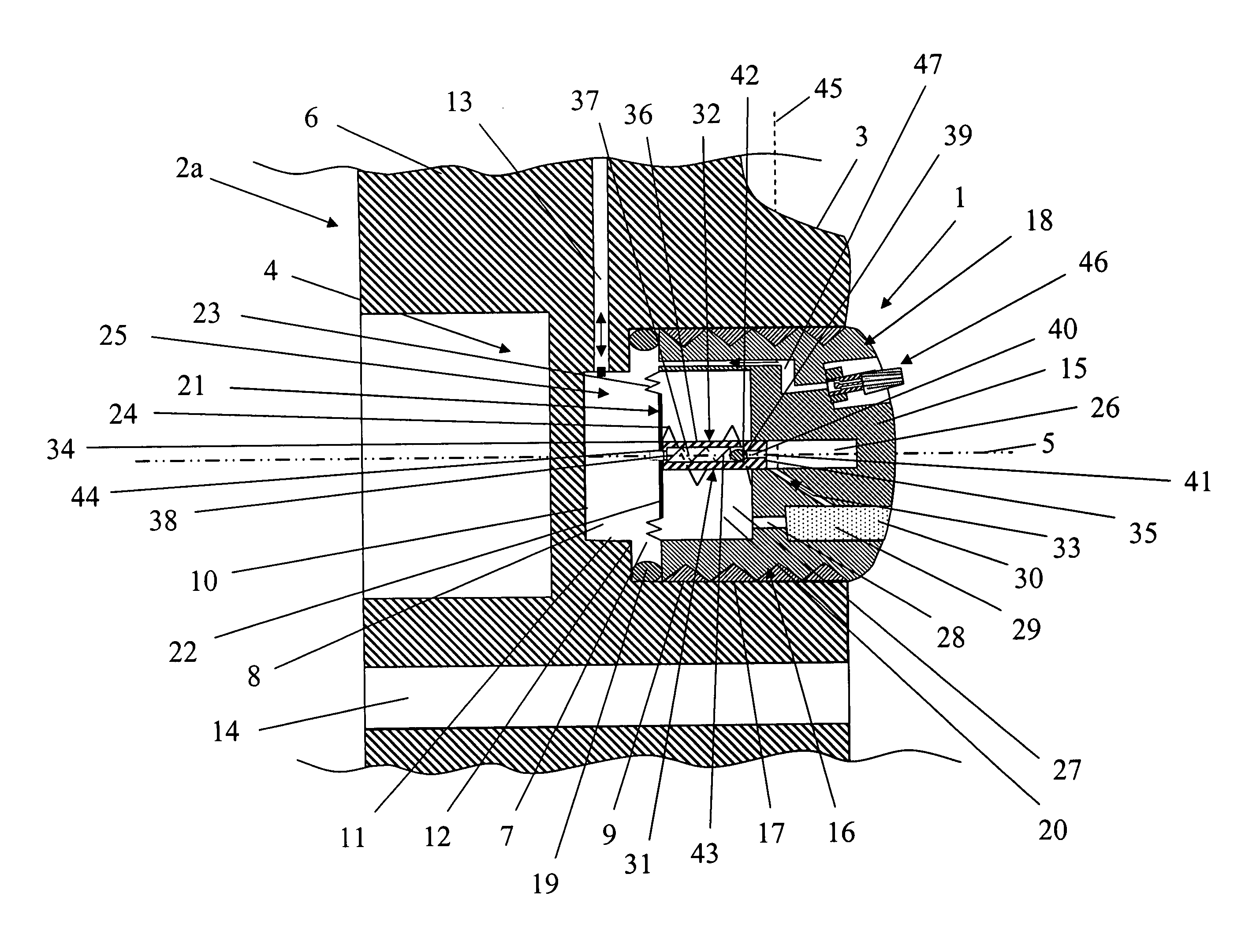
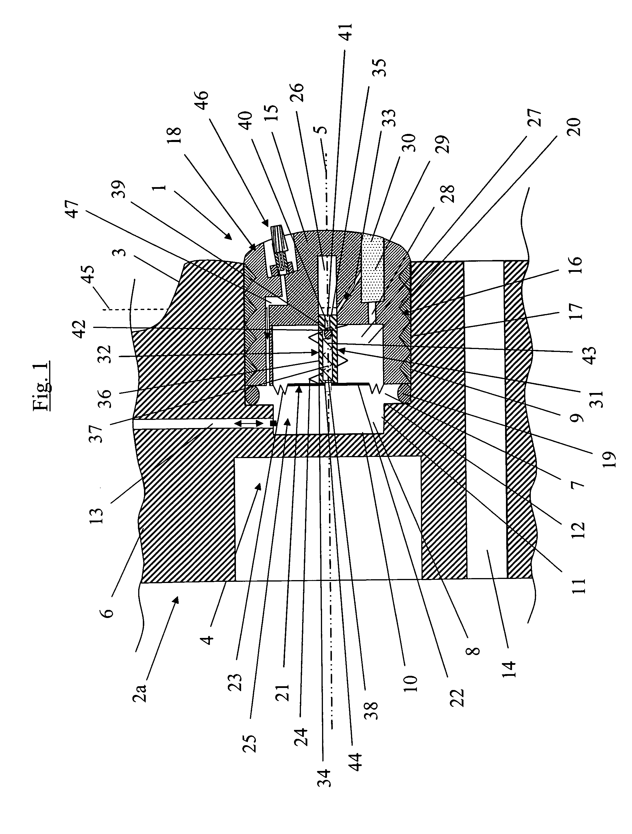
[0031]FIG. 1 schematically teaches a cross-section of a tire pressurizing device 1 according to the invention mounted on a wheel 2. The wheel 2 comprises a load bearing tire (not shown) mounted on a rim (not shown) comprising a tire volume comprising compressed air with a predetermined tire pressure. The wheel also comprises a wheel disc 2a (or nave) joined to the rim. The tire pressurizing device 1 is arranged for automatically pressurizing the load-bearing tire during rotation thereof over a surface.

[0032]FIG. 1 shows only a part of the wheel disc 2a comprising a central part 4 with a central axis. The wheel disc 2a comprises a number of spokes 6 extending in the radial direction from the central part 4 to the rim. The central part is arranged with a cylindrical opening 7 and a cylindrical cavity 8 with a lesser diameter than the cylindrical opening 7 and arranged in fluid communication with the cylindrical opening 7. In FIG. 1, the cylindrical cavity 8 is arranged coaxially with ...

second embodiment

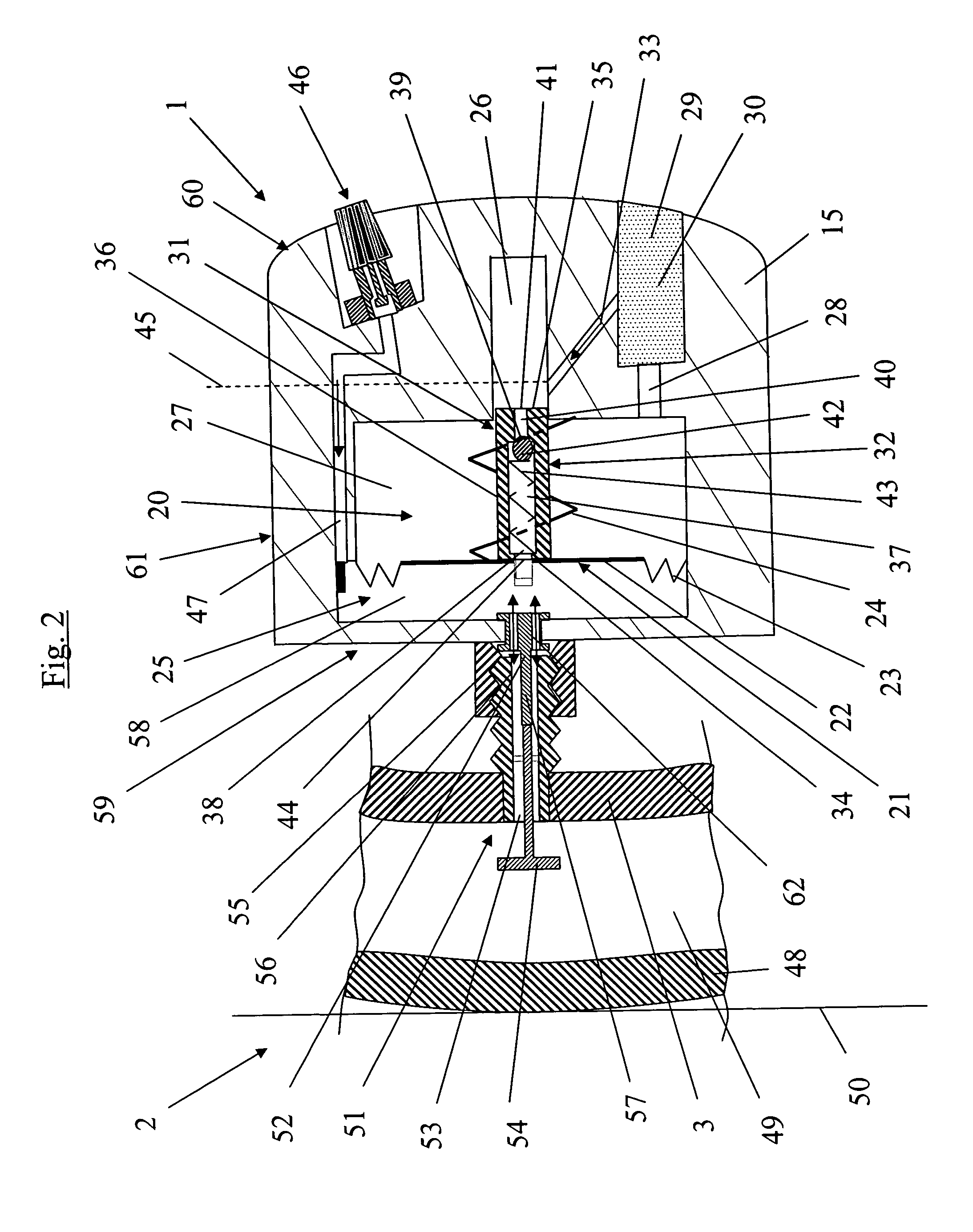
[0045]FIG. 2 schematically teaches a cross-section of a tire pressurizing device 1 according to the invention mounted on a wheel 2. FIG. 2 shows a part of the rim 3 and the tire 48 and the therebetween enclosed tire volume 49. In FIG. 1 the tire 48 rolls over a ground surface 50.

[0046] The compression unit 31 and the membrane 21 described in connection to FIG. 1 is the same as in FIG. 2. In FIG. 2, the tire pressurizing device 1 is in the negative position as in FIG. 1.

[0047] In FIG. 2, the wheel 2 comprises a third air valve 51 intended to be used for inflating and deflating the tire. The third air 51 valve is mounted on the rim 3. The third air valve 51 comprises an opening 52 and a third air valve conduit 53 opening out into the tire volume 49. The third air valve conduit 53 comprises a non-return valve 54 for closing the third air valve conduit 53 from letting out compressed air from the tire volume 49.

[0048] In FIG. 2, the pressurizing device 1 is mounted to the wheel 2 via t...

third embodiment

[0057]FIG. 6 schematically teaches a cross-section of a tire pressurizing device 1 according to the invention mounted on a wheel 2, where the tire pressurizing device 1 is in a negative position. FIG. 6 differs from FIG. 2 only in that an adjusting means 65 in the form of a bolt, or the like, is arranged in the housing 15 and being part of the compression chamber enclosure. The adjusting means 65 may be moved in the sliding direction for diminishing the volume of the compression such that different air pressures may be reached in the compression chamber 26 for a given piston 32 movement and a given resilient strength of the second resilient means 43. The smaller the volume of the compression chamber 26 the larger the pressure of the compressed air.


PUM


Abstract

The invention refers to a pneumatic tire pressurizing device for automatically pressurizing a load-bearing tire during rotation thereof over a surface, said tire comprising a tire volume comprising compressed air having a predetermined tire pressure. The pressurizing device comprises a compression unit connected to a movable device. The pressurizing device is connectable to a wheel comprising the tire, and when connected to the wheel the compression unit is arranged to compress air in the compression chamber when the movable device, starting from a negative position, is affected by a sudden increase of the tire pressure due to deformation of the tire when passing an irregularity in the surface, wherein said compression unit is arranged to feed the compressed air in the compression chamber to the tire volume via the pressure chamber.

Description

TECHNICAL FIELD [0001] The invention refers to a pneumatic tire pressurizing device for automatically pressurizing a load-bearing tire during rotation thereof over a surface. The pressurizing device comprises a housing encompassing an inner space. The tire comprises a tire volume comprising compressed air having predetermined tire pressure. BACKGROUND ART [0002] Vehicles are equipped with wheels that rotate over a surface when the vehicle is moved. Most vehicles use a wheel comprising a tire fitted onto a rim which is mounted on a wheel disc. In the field of vehicles it is known that the tire pressure of the wheel is of the utmost importance for the performance of the vehicle. Therefore, all vehicle users are informed via manuals what predetermined tire pressure is suitable for what operating condition, i.e. load, speed, etc. One problem with the wheel arrangements of today is that air slowly leaks from the tire. Even though the leakage is small it forces the user of the vehicle to ...

Claims


Application Information

Patent Timeline
Patent Type & Authority Applications(United States)
IPC IPC(8): B60C23/10B60C23/12
CPCB60C23/12B60C23/126B60C23/135
Inventor WESSMAN, BJORN SR.
Owner FORD GLOBAL TECH LLC
Why Eureka
Try Eureka