Lateral boring system

a technology of lateral boring and lateral borehole, which is applied in the direction of drilling pipes, drilling rods, directional drilling, etc., can solve the problems of low drill bit power, unable to allow the flexible shaft to extend deeper, and the blade to penetrate through, etc., to achieve the effect of simple and effectiv

Inactive Publication Date: 2005-12-22
SCHELLING ANTHONY HOWARD
View PDF6 Cites 0 Cited by
  • Summary
  • Abstract
  • Description
  • Claims
  • Application Information

AI Technical Summary

Benefits of technology

[0005] The present invention solves these problems and others by providing a simple and effective lateral boring device for underground installation of utility equipment. The device consists of a hand-held drill, a flexible shaft attachable at one end to the drill, a bit and blade attachable to the other end of the flexible shaft, and a metal sock for retrieving the utility equipment after the boring has been completed.
[0007] Another aspect of the invention allows the user to adjust the angle of entry to accomplish longer or shorter runs more effectively, and reduce the overall length of the borehole.

Problems solved by technology

The low power of the drill does not enable the flexible shaft to extend deeper than the hardpan beneath the ground soil, nor does it allow the blade to penetrate through the obstacle material.

Method used


Image

  • Lateral boring system
  • Lateral boring system
  • Lateral boring system

Examples


Embodiment Construction

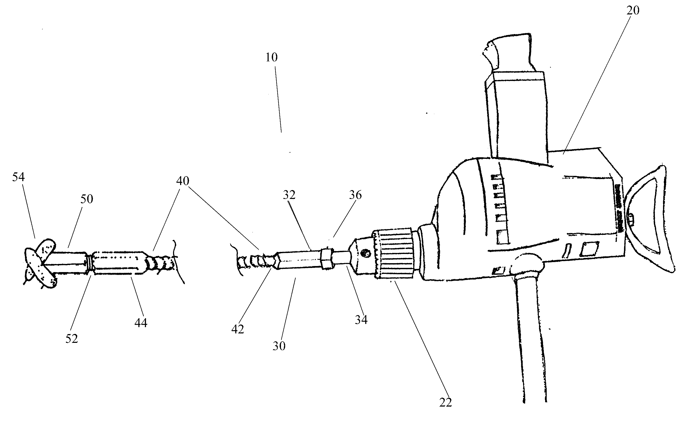
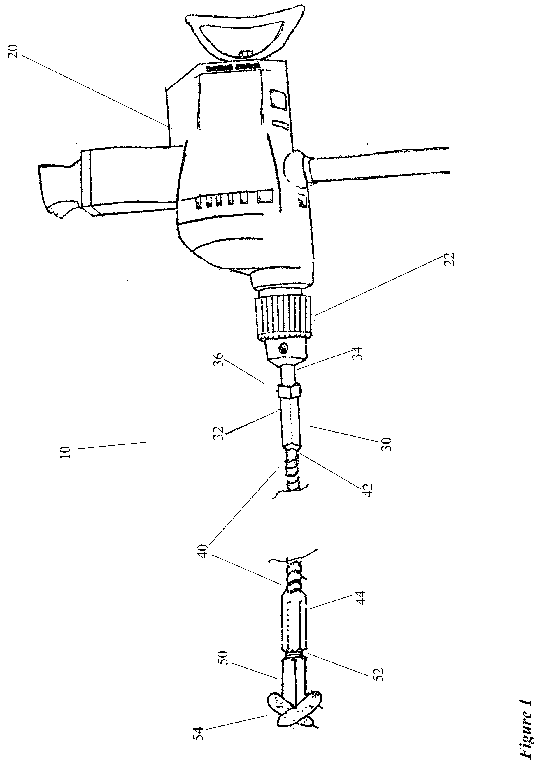
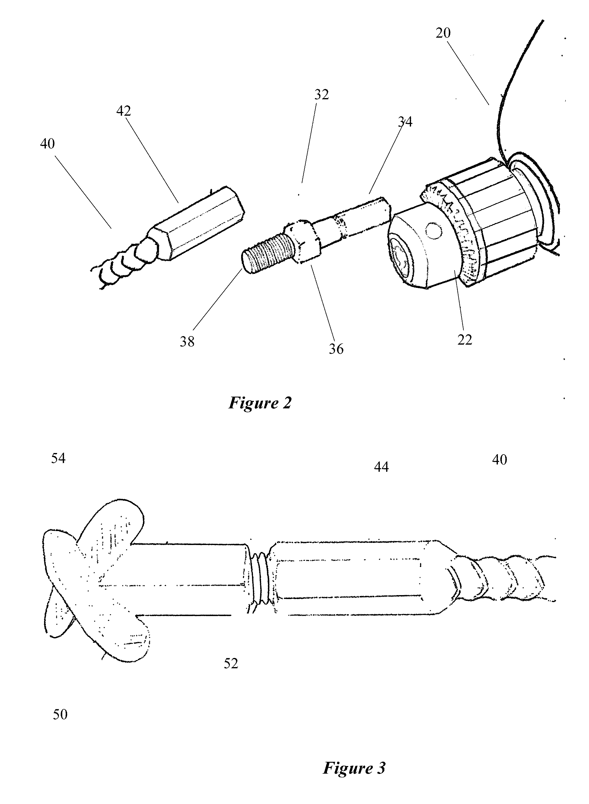
[0015] The present invention provides a tool capable of laterally boring for the placement of underground cables, wires, pipe and other equipment. Referring in more detail to the drawings, as shown in FIGS. 1-5, a preferred embodiment of the present invention is described. It is to be expressly understood that this exemplary embodiment is provided for descriptive purposes only and is not meant to unduly limit the scope of the present inventive concept. Other embodiments, and variations of the hand-held drive assembly or flexible shaft of the present invention are considered within the present inventive concept as set forth in the claims herein. For explanatory purposes only, the apparatus of the preferred embodiments are discussed primarily for the purposes of understanding the method of underground boring. It is to be expressly understood that other boring equipment are contemplated for use with the present invention as well.

[0016] A preferred embodiment of the present invention i...


PUM


Abstract

A lateral boring device for effective utility installation under sidewalks, driveways, and other obstacles. The present invention utilizes a hand-held drill, a flexible shaft, a blade attachable to the flexible shaft, and a metal sock. The operator of the present invention makes an incision into the ground with the blade in close proximity to the obstacle intended to be circumvented. The operator commences boring, and the flexible shaft begins to descend below the ground and underneath the obstacle. The low power of the drill prevents the flexible shaft from continuing to descend below the hardpan, and cause the flexible shaft to bend in a generally upwardly horizontal direction. The low power of the drill also prevents the flexible shaft or the blade from causing damage to the underside of the obstacle, and eventually the flexible shaft resurfaces on the opposite side of the obstacle. Upon resurfacing, the operator removes the blade and attaches the sock, which can be coupled to the length of wire, pipe or conduit and pulled back through the bore hole.

Description

BACKGROUND OF INVENTION [0001] Typically wire, cabling, pipe and other equipment installed for providing power, signal, water, or some other medium are placed underground. The reasons for this are to protect and insulate the medium passing through this equipment, and also to eliminate the unpleasing aesthetic appearance of the multitude of these wires, cables and pipes necessary to provide buildings with the necessary utilities and services. [0002] One prior method for placing these types of underground equipment was to dig a trench along the path desired to place the equipment. The equipment could be placed in the bottom of the trench and covered up. One disadvantage of this method was the damage to the land caused by the trenching. Another disadvantage is the damage to permanent structures in the path of the equipment, such as sidewalks, driveways, highways and other surfaces. [0003] Currently there are a variety of boring methods for alleviating the disadvantages inherent with tr...

Claims


Application Information

Patent Timeline
Patent Type & Authority Applications(United States)
IPC IPC(8): E21B7/04E21B7/26E21B10/26E21B11/00E21B17/20
CPCE21B7/046E21B17/20E21B11/005
Inventor SCHELLING, ANTHONY HOWARD
Owner SCHELLING ANTHONY HOWARD
Why Eureka
Try Eureka