Processing method for conservation of processing gases

a processing method and gas technology, applied in the field of processing equipment, can solve the problems of reducing the ability of evacuation, and not having a fully functioning gas circulating mechanism, and achieve the effect of controlling the circulating gas with eas

Inactive Publication Date: 2005-12-22
TOSHIBA MEMORY CORP
View PDF4 Cites 19 Cited by
  • Summary
  • Abstract
  • Description
  • Claims
  • Application Information

AI Technical Summary

Benefits of technology

[0009] An object of the present invention, which has been completed by addressing the problem of the processing apparatus in the prior art discussed above, is to provide a new and improved processing apparatus capable of controlling the circulating gas with ease.

Problems solved by technology

If the back-pressure of the turbo pump exceeds the rated back-pressure, the evacuating capability becomes greatly reduced.
As described above, while the processing apparatus in the prior art may be considered effective in reducing emission the processing gas and the quantity of processing gas consumption by recycling the processing gas, it is not equipped with a fully functioning gas circulating mechanism.
Namely, when a circulating gas piping is provided between the downstream side of the evacuating mechanism sand the upstream side of the gas supply mechanism as in the processing apparatus in the prior art, a problem arises in that efficient gas circulation is not achieved since the back-pressure of the evacuating mechanism is approximately 10 Torr and the pressure on the upstream side of the gas supply mechanism can be lowered only down to several Torr˜several tens of Torr.

Method used


Image

  • Processing method for conservation of processing gases
  • Processing method for conservation of processing gases
  • Processing method for conservation of processing gases

Examples


first embodiment

[0036] The first embodiment of the present invention is now explained.

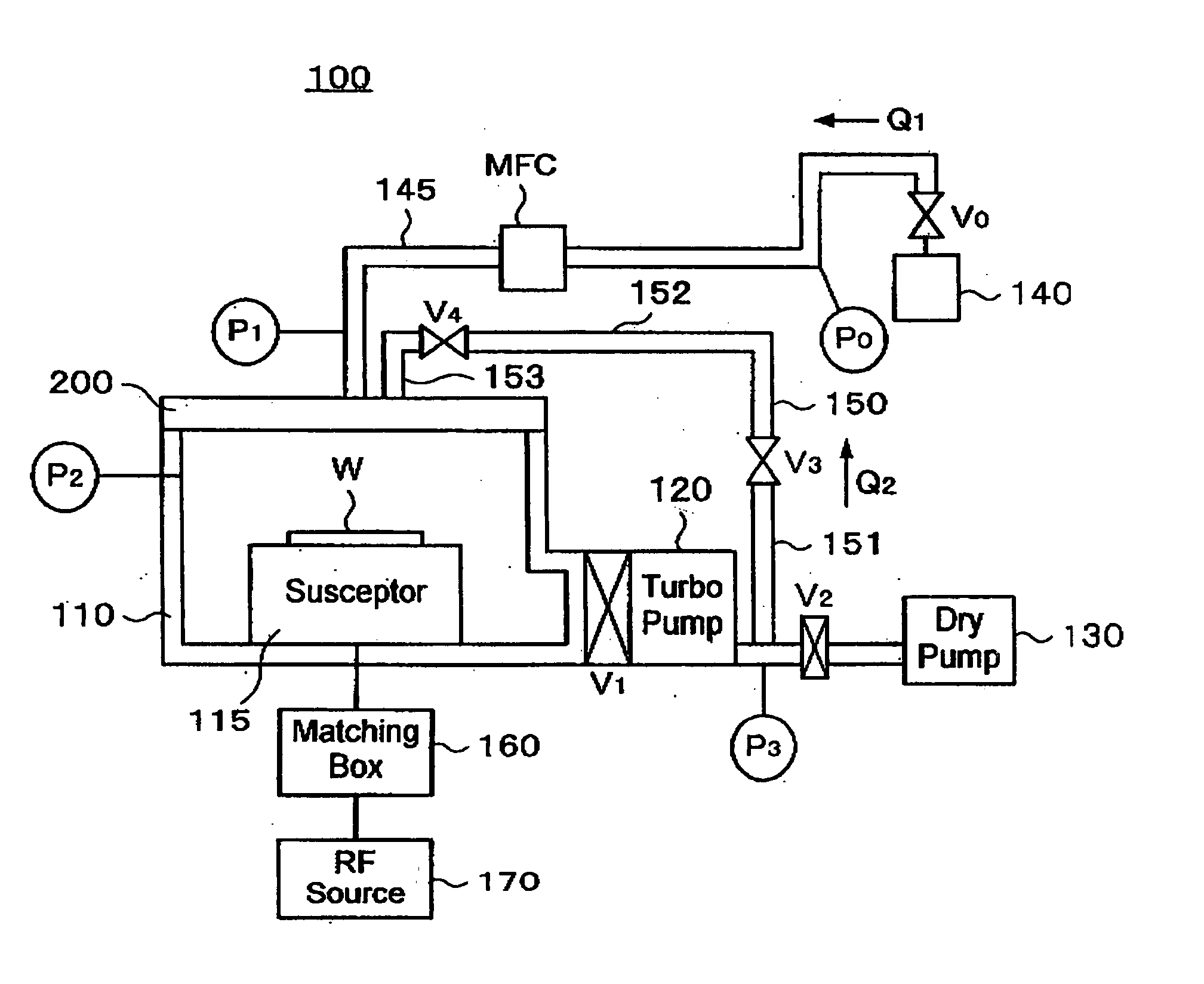
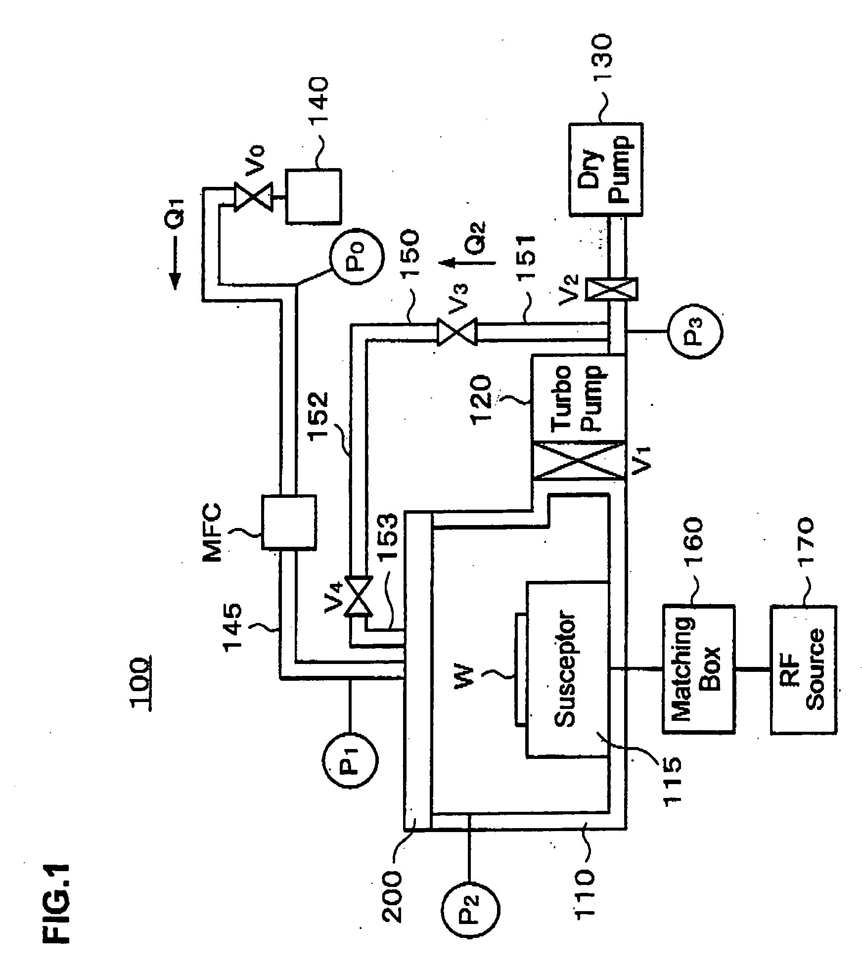
[0037] A processing apparatus 100 in the embodiment is explained in reference to FIG. 1. It is to be noted that FIG. 1 schematically illustrates the internal structure of the processing apparatus 100.

[0038] (Processing Apparatus 100)

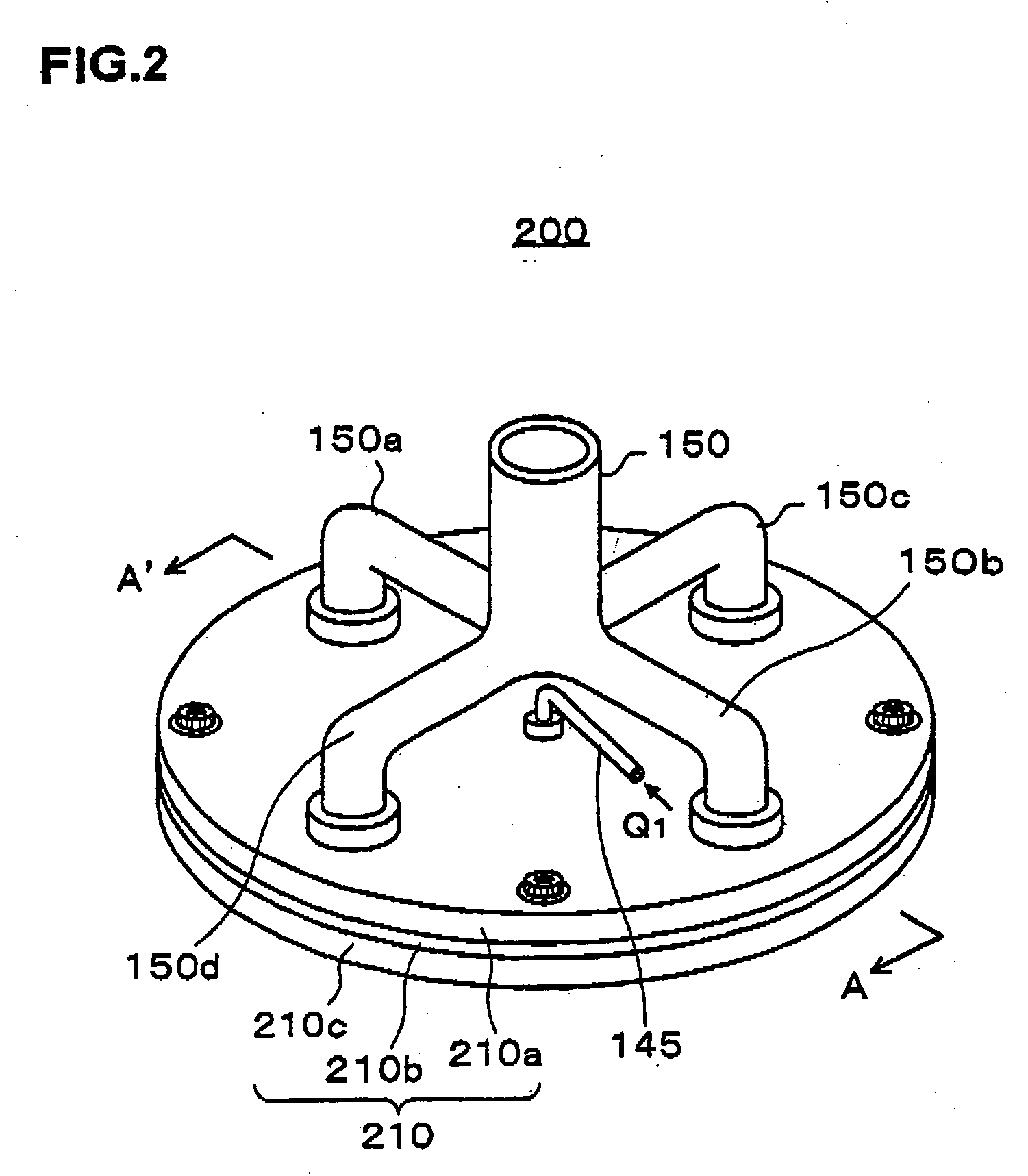
[0039] As shown in FIG. 1, the processing apparatus 100 mainly comprises a processing chamber 110, a showerhead 200 provided in the upper portion of the processing apparatus 100, which constitutes an example of a gas supply mechanism for supplying a process gas into the processing chamber 110 via a plurality of gas supply holes, a turbo pump 120 constituting an example of an evacuating mechanism for evacuating the processing gas from the processing chamber 10, a dry pump 130 for further evacuating the processing gas to reduce the pressure on the downstream side of the turbo pump 120, a primary gas piping 145 through which the processing gas (primary gas) Q1 supplied from a gas sourc...

second embodiment

[0111] The second embodiment of the present invention is now explained.

[0112] As illustrated in FIG. 8, the processing apparatus in the embodiment is characterized by a second primary gas piping 148 provided to supply the primary gas Q1 through the circulating gas supply holes and a valve V5 constituting a means for flow rate adjustment for the primary gas Q1 provided at the second primary gas piping 148. It is to be noted that components other than the second primary gas piping 148 and the valve V5 assume structures identical to those in the first embodiment.

[0113] In the embodiment, the circulating gas supply holes h2 can be utilized as supply holes for the primary gas Q1 when processing which does not require the circulating gas Q2 is implemented. In such a case, with the valve V5 provided at the second primary gas piping 148, better flow control is achieved when supplying the primary gas Q1 through the circulating gas supply holes h2. As a result, an improvement is achieved in...


PUM

PropertyMeasurementUnit
back-pressureaaaaaaaaaa
pressureaaaaaaaaaa
pressureaaaaaaaaaa

Abstract

In order to facilitate control of a circulating gas, in a processing apparatus 100 having a showerhead 200 for supplying a processing gas into a processing chamber via a plurality of gas supply holes, a turbo pump 120 for evacuating the processing gas from the processing chamber 110 and a circulating gas piping 150 for returning at least a portion (circulating gas Q2) of the exhaust gas evacuated from the processing chamber by the turbo pump to the showerhead, the showerhead is provided with a primary gas supply system that supplies a primary gas Q1 supplied from a gas source 140 into the processing chamber via a plurality of primary gas outlet holes h1 and a circulating gas supply system that supplies the circulating gas into the processing chamber via a plurality of circulating gas supply holes h2, with the primary gas supply system and the circulating gas supply system constituted as systems independent of each other. Since the primary gas and the circulating gas are allowed to become mixed only in the processing chamber, the circulating gas can be controlled with a greater degree of ease without having to implement pressure control.

Description

BACKGROUND OF THE INVENTION [0001] 1. Field of the Invention [0002] The present invention relates to a processing apparatus. [0003] 2. Description of the Related Art [0004] Gases containing great quantities of fluorine atoms are used as etching gases in etching technologies in order to develop a reaction seed containing fluorine through plasma discharge or the like. As increasingly vigorous efforts have been made to protect the global environment on an international scale in recent years, global warming, in particular, is one of the most important issues to be addressed. Under these circumstances, reduction in the quantity of atmospheric emissions of fluorine compounds used in dry etching technologies in the prior art, which have long atmospheric life and high global warming coefficients, has become an urgent goal that we must achieve to prevent further global warming. [0005] As a means for reducing the emission quantity of the processing gas containing fluorine compounds in the dry...

Claims


Application Information

Patent Timeline
Patent Type & Authority Applications(United States)
IPC IPC(8): H01L21/3065B44C1/22H01L21/00
CPCH01J37/3244H01J37/32449H01J37/32834H01L21/76897H01L21/67069H01L21/76802H01L21/31116H01L21/3065
Inventor SAITO, MASASHIHIRAYAMA, YUSUKESAKAI, ITSUKOOHIWA, TOKUHISA
Owner TOSHIBA MEMORY CORP
Why Eureka
Try Eureka