Self-contained, portable and automatic fluid dispenser

a self-contained, portable, automatic technology, applied in the direction of liquid transfer devices, instruments, horology, etc., can solve the problems of liquid being dispensed with a time delay, malfunctioning mounted automatic dispensers, high price of mounted automatic dispensers, etc., and achieve the effect of high fluid level in the shaft combination

Inactive Publication Date: 2005-12-22
TOUCH FREE APPL
View PDF6 Cites 25 Cited by
  • Summary
  • Abstract
  • Description
  • Claims
  • Application Information

AI Technical Summary

Benefits of technology

[0010] The container has a cylindrical neck portion. The sleeve reservoir is first inserted through the neck portion into the container before fluid is poured into the container. Excess fluid overflows from the overflow openings of the sleeve into the container. With the housing resting on top of the container, the shaft combination of the pump assembly is inserted co-axially into the sleeve reservoir within the container, submerging the shaft combination in the fluid. The fluid floods the space between the helical shaft and the pipe of the shaft combination. As a result, upon initial rotation of the helical shaft, fluid is dispensed from the nozzle of the housing with minimal delay. When fluid is drawn upward by the helical shaft and is dispensed, the fluid in the sleeve reservoir is continuously replenished from the container through the ball valve, thereby maintaining a high level of fluid in the shaft combination.

Problems solved by technology

Disadvantageously, this type of dispenser requires the user to push the lever or pump handle numerous time upon initial use to draw sufficient fluid upward for dispensing at the nozzle.
When this type of dispenser has not been used for a period of time, fluid in the pump sometimes flows back to the soap container due to gravity and again requires numerous pumping before fluid is dispensed.
Disadvantageously, these type of mounted automatic dispensers are expensive and not portable.
Further, a malfunctioned mounted automatic dispenser requires either a technician for on-site servicing or a technician for often complicated disassembling of the dispensers for off-site servicing.
Similar to the plunger pump dispensers, disadvantageously, liquid is dispensed with a time delay since it requires numerous rotation of the helical pump to draw sufficient fluid upwards for dispensing at the nozzle.
Further, liquid in the helical screw pump is more prone to flow back to the liquid container than the plunger pump, thereby resulting in time delay in dispensing liquid each time the dispenser is used.
Another disadvantage is that this prior art liquid dispenser cannot be used to dispense fluid with high viscosity, such as gel, because the rotation of the helical screw pump against the gel along the helical pump causes the viscosity characteristic to break down and liquefies the gel.

Method used


Image

  • Self-contained, portable and automatic fluid dispenser
  • Self-contained, portable and automatic fluid dispenser
  • Self-contained, portable and automatic fluid dispenser

Examples


Embodiment Construction

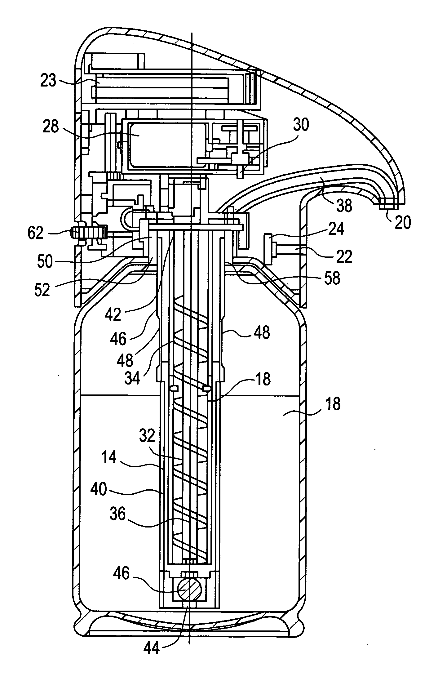
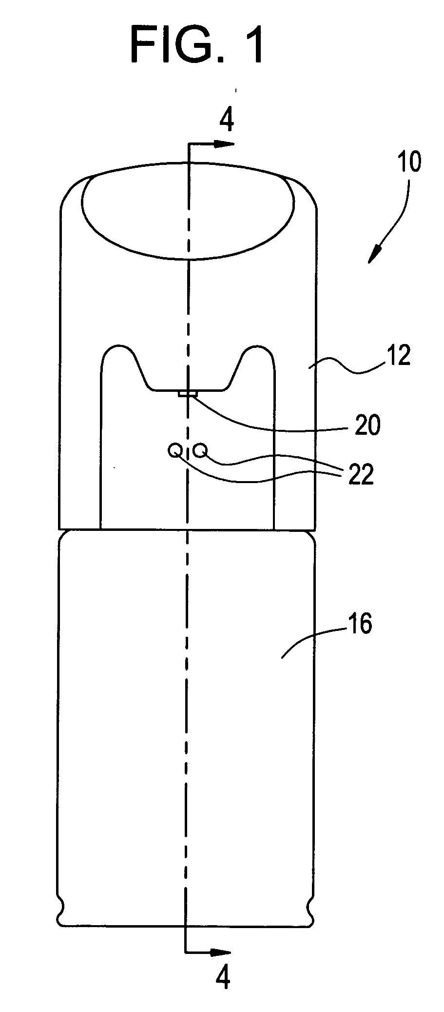
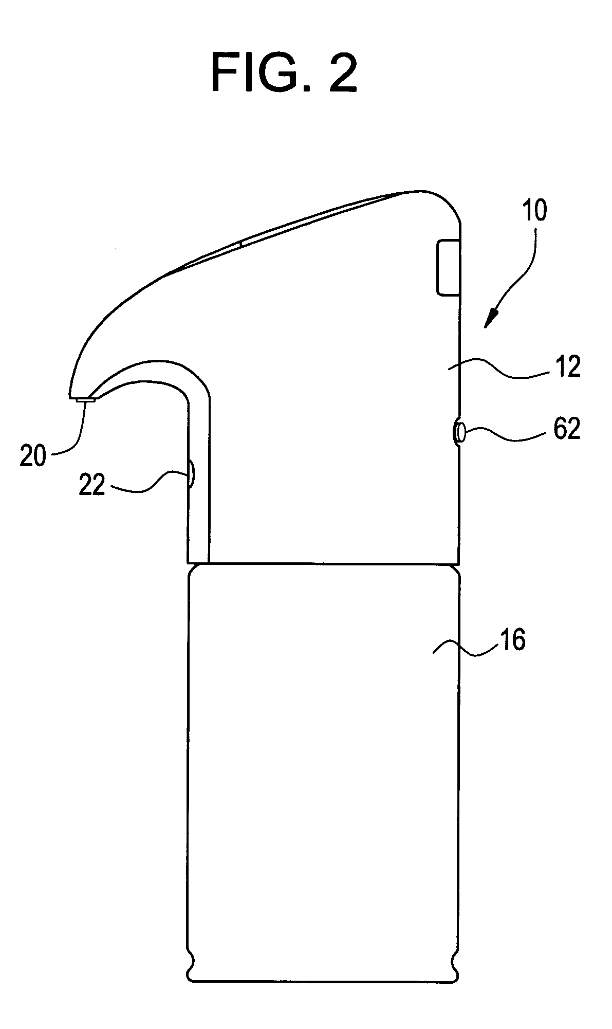
[0017] With reference to the drawings, wherein the same reference number indicates the same element throughout, there is shown in FIGS. 1-3 a fluid dispenser 10 of the present invention. Fluid dispenser comprises a housing 12, a sleeve reservoir 14 and a container 16 for storing fluid 18. Housing 12 sits on top of and correspondingly mates with container 16.

[0018] Housing 12 has a nozzle 20 for dispensing fluid 18 from the container 16. Nozzle is preferably extended slightly beyond the housing 12 to prevent droplets of fluid 18 from forming at the nozzle 20. The housing 12 has a sensor 22 that detects the presence of a user's hand or an object to dispense fluid 18 from the container 16. Sensor 22 is preferably an infrared sensor, which is known to one skilled in the art of electronics. Housing 12 contains the power source 23 and an integrated circuit (IC) chip 24 and a pump assembly 26. Power source 23 is shown as a plurality of batteries. However, the fluid dispenser 10 may be ada...


PUM


Abstract

A fluid dispenser includes a housing, a sleeve reservoir and a container. The housing has a nozzle for dispensing the fluid and contains a power source, an infrared sensor, an integrated circuit chip and a pump assembly. The pump assembly includes a motor, at least one gear, a pipe and a helical shaft positioned coaxially within the pipe. The helical shaft is driven rotatingly relative to the pipe. The sleeve reservoir has open upper and lower ends, overflow openings near the upper end and a ball valve at the lower end. The sleeve reservoir is first inserted into the container before fluid is poured into the container. The helical shaft and pipe are then inserted co-axially into the sleeve reservoir, submerging them in the fluid and flooding the space between the helical shaft and the pipe to minimize the time delay for dispensing the fluid.

Description

FIELD OF THE INVENTION [0001] The invention relates to a device for dispensing fluid. In particular, a self-contained, portable and automatic fluid dispenser that is capable of dispensing fluid of various viscosity. BACKGROUND OF THE INVENTION [0002] Dispensers of fluid or liquid are commonly used in industrial, business, residential and hospital settings. The most common type of fluid dispensers have plunger pumps with the soap container at the bottom wherein a user pushes a lever or handle downward to draw fluid upward for ejection at a nozzle near the top. Disadvantageously, this type of dispenser requires the user to push the lever or pump handle numerous time upon initial use to draw sufficient fluid upward for dispensing at the nozzle. When this type of dispenser has not been used for a period of time, fluid in the pump sometimes flows back to the soap container due to gravity and again requires numerous pumping before fluid is dispensed. [0003] Since fluid dispensers are ofte...

Claims


Application Information

Patent Timeline
Patent Type & Authority Applications(United States)
IPC IPC(8): B05B9/08B05B12/12B67D7/08G04C23/00
CPCB05B9/0861B05B12/122B05B9/0866
Inventor LO, RAYMOND
Owner TOUCH FREE APPL
Why Eureka
Try Eureka